Equipment for producing biochar from rice straw and technology for producing biochar

A technology of rice straw and production equipment, applied in the field of biochar production equipment and technology, can solve the problems of high process energy consumption, long production cycle, short production cycle, etc., and achieve simple production process, large apparent specificity, and short production cycle Effect

Active Publication Date: 2017-03-08
CAPITAL NORMAL UNIVERSITY
View PDF8 Cites 3 Cited by
  • Summary
  • Abstract
  • Description
  • Claims
  • Application Information

AI Technical Summary

Problems solved by technology

[0006] The technical problem to be solved by the present invention: the current rice straw biochar production equipment and the process for producing biochar have high energy consumption, long production cycle and poor controllability of the production process, resulting in high production cost of biochar and the apparent appearance of

Method used


Image

  • Equipment for producing biochar from rice straw and technology for producing biochar
  • Equipment for producing biochar from rice straw and technology for producing biochar
  • Equipment for producing biochar from rice straw and technology for producing biochar

Examples


Embodiment 1

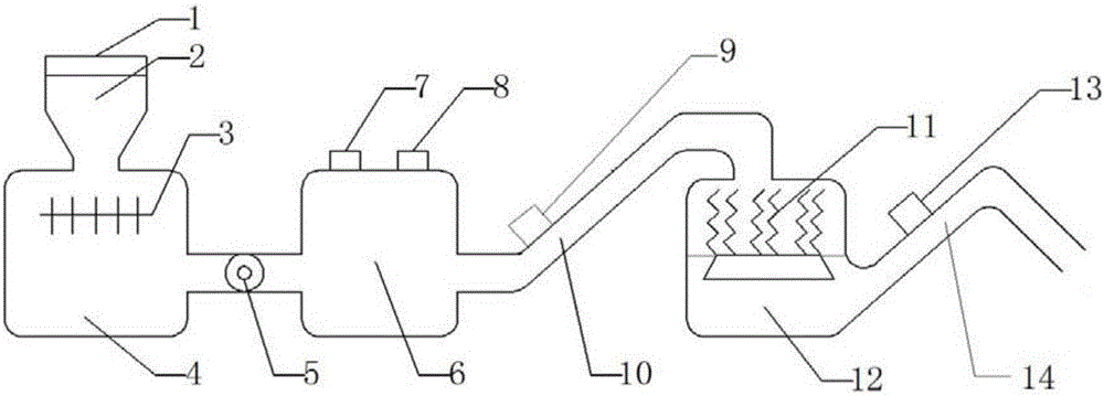
[0034] figure 1 The first embodiment of the present invention is given as figure 1 As shown, a rice straw biochar production equipment includes a feed box 2, a pulverizer 4, a reaction vessel 6, a discharge conveying pipe 10, a cracking box 11, a furnace 12, a first cooler 9, and a second cooler 13 , the feed box 2 is located above the pulverizer 4, the feed box 2 is provided with a feed port 1, the pulverizer 4 is provided with a pulverizing blade 3, the pulverizer 4 and the reaction vessel 6 The room is connected by a discharge valve 5, the reaction vessel 6 is provided with a heater 8 and a pressurizing device, the discharge delivery pipe 10 is connected between the reaction vessel 6 and the furnace 12, and the first cooler 9 is provided with At the outlet connection of the reaction vessel 6, the cracking box 11 is located above the stove 12, and the side wall of the stove 12 is also provided with a discharge pipe 14, and the second cooler 13 is located on the discharge pi...

Embodiment 2

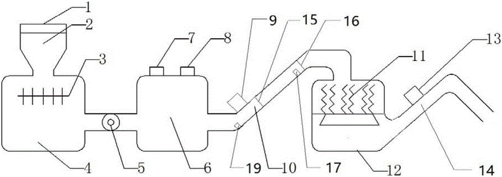
[0038] figure 2 Provided the 2nd embodiment of the present invention, as figure 2 , Figure 4As shown, the difference between embodiment 2 and embodiment 1 is that one end of the discharge conveying pipe 10 close to the reaction vessel 6 is also provided with a lower gate 15, and the other end is provided with an upper gate 16, and in the discharge conveying pipe 10 Near the position of the upper gate 16, a feed amount detection sensor 17 is provided, and the feed amount detection sensor 17 is used to detect the feed amount of the cracking box 11, and is connected with the lower gate 15, the upper gate 16 and the feed amount. The detection sensor 17 is connected with an MCU18, and a display screen is connected with the MCU18. The MCU18 is pre-stored with cracking box 11 feed amount preset data, and the MCU18 is controlled according to the feed amount data collected by the feed amount detection sensor 17. The opening and closing of the lower gate 15 and the upper gate 16. ...

Embodiment 3

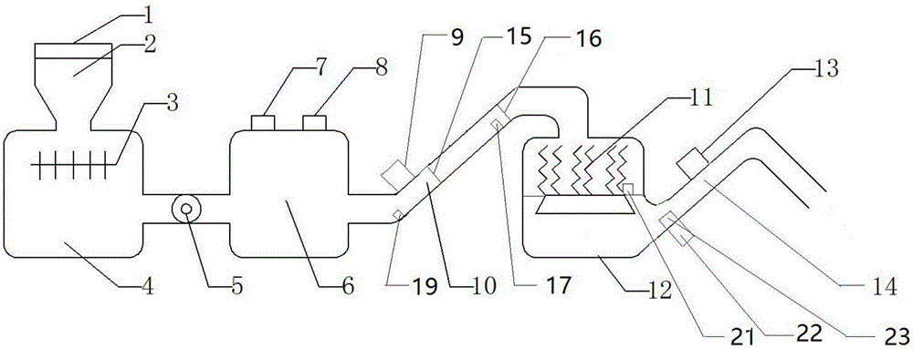
[0043] image 3 Provided the 3rd embodiment of the present invention, as image 3 As shown, the difference between embodiment 3 and embodiment 2 is that the bottom of the cracking box 11 is also provided with a tar catalyst chamber 21, and a tar catalyst is arranged in the tar catalyst chamber 21.

[0044] The outlet of the furnace 12 is also provided with a tar separator 23, and a tar cracking chamber 22 is connected with the tar separator 23, and a tar waste gas exhaust pipe is connected with the tar cracking chamber 22.

[0045] Embodiment 3 all the other are identical with embodiment 2.


PUM


Abstract

The invention discloses equipment for producing biochar from rice straw. The equipment comprises a feeding box, a pulverizator, a reaction vessel, a discharge delivery pipe, a pyrolysis box, a heating stove, a first cooler and a second cooler. Meanwhile, the invention discloses a technology for producing the biochar. The method comprises steps as follows: firstly, the rice straw enters the feeding box through a feed inlet and then enters the pulverizator for pulverization; the pulverized rice straw enters the reaction vessel through a discharge valve and is processed, the processed rice straw is cooled by the first cooler, is sent to the pyrolysis box through the discharge delivery pipe for high-temperature pyrolysis and then is conveyed to the heating stove for carbonization, and the carbonized rice straw is discharged from a discharge port after cooled by the second cooler. The production technology is simple, the energy consumption of the equipment is low, and the cost is lower than that of other methods by 8% or more; the production cycle is short, the controllability of a production process is high, and apparent specific gravity of the obtained biochar is high.

Description

technical field [0001] The invention belongs to the technical field of biochar production equipment and technology, and relates to rice straw biochar production equipment and a process for producing biochar. Background technique [0002] With the increase of crop production year by year, the development of rural urbanization and the further improvement of farmers' living standards, the output of crop straw has increased significantly. At the same time, the proportion of straw used as firewood has gradually declined, and a large amount of surplus straw has been abandoned on the fields and roadsides. Or ditches, or burning at the head of the field, has brought great hidden dangers to the ecological environment and the safety of life and property. my country is a major rice producing country, and a large amount of rice straw is produced every year. Rice straw is a by-product obtained after rice threshing and seed harvesting. The threshing stem and attached dry leaves become str...

Claims


Application Information

Patent Timeline
IPC IPC(8): C10B53/02C10B57/06C10B57/00
CPCC10B53/02C10B57/00C10B57/06Y02E50/10
Inventor 张玉虎赵远侯国军杨泽平孙辰鹏潘韬
Owner CAPITAL NORMAL UNIVERSITY
Why Eureka
Try Eureka