Electric hydraulic excavator

A technology for hydraulic excavators and electric motors, applied to mechanically driven excavators/dredgers, earth movers/shovels, construction, etc. Problems such as large motor size and high motor cost can achieve the effect of increasing energy recovery and auxiliary functions, convenient power supply, and improving energy efficiency

Inactive Publication Date: 2017-03-08
湖南德力重工科技股份有限公司
View PDF6 Cites 5 Cited by
  • Summary
  • Abstract
  • Description
  • Claims
  • Application Information

AI Technical Summary

Problems solved by technology

A main motor is used to drive three hydraulic pumps through the shaft. Correspondingly, both the main motor and the frequency converter need to meet the maximum power requirements of the machine operation, resulting in a single motor with large volume and slow dynamic response.
Both the main motor and the rotary motor use rare earth permanent magnet synchronous motors, and the cost of the motors is very high
Moreover, the invention patent only discloses the power source part of the electric excavator, and does not give the circuit principle and control scheme of the specific hydraulic system of the excavator.

Method used


Image

  • Electric hydraulic excavator
  • Electric hydraulic excavator
  • Electric hydraulic excavator

Examples


Embodiment 1

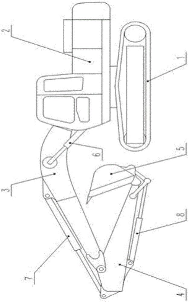
[0038] Example 1: figure 1 As shown, an electro-hydraulic excavator, the mechanical system includes a traveling body 1, a rotating body 2 arranged on the traveling body 1, a boom 3 connected with the rotating body to rotate up and down, and an arm mounted on the front end of the boom 4. A bucket 5 installed at the front end of the stick 4, a pair of boom hydraulic cylinders 6 for driving the boom 3, a stick hydraulic cylinder 7 for driving the stick 4, and a bucket hydraulic cylinder 8 for driving the bucket. The driver's control room is set on the rotating body 2, and the rotating body 2 is installed on the running body 1. The driver operates the driving body 1, rotating body 2, boom 3, stick 4, and bucket 5 respectively or in combination. Excavation of soil and sand, bulldozing, or rolling operations to tighten the ground.

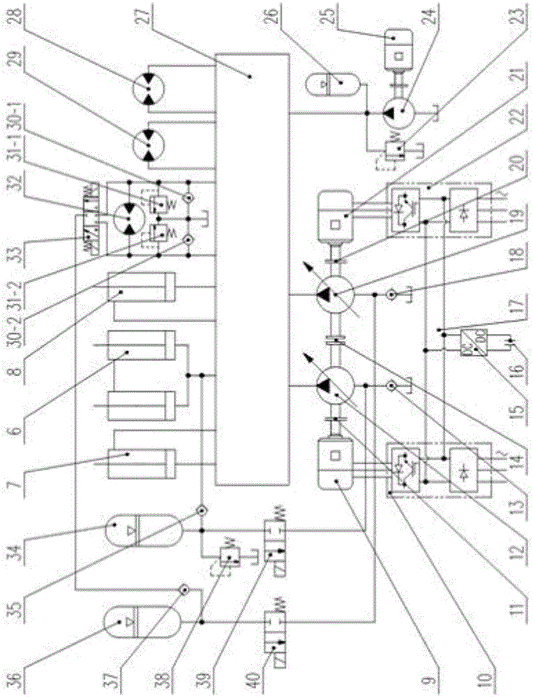
[0039] figure 2 As shown, the control system, the boom hydraulic cylinder 6, the stick hydraulic cylinder 7, the bucket hydraulic cylinder 8, the swi...

Embodiment 2

[0051] Embodiment 2: as Figure 4 As shown, the difference between this embodiment and Embodiment 1 lies in the accumulator auxiliary circuit: the first hydraulic pump 12 and the second hydraulic pump 19 are simultaneously assisted by the low-pressure accumulator 34 or the high-pressure accumulator 36 . The oil outlets of the high-pressure accumulator 36 and the low-pressure accumulator 34 are connected to two oil inlets of the second three-position three-way electromagnetic reversing valve 43, and the oil outlets of the second three-position three-way electromagnetic reversing valve 43 are connected to the The oil suction port of the first hydraulic pump 12, the oil outlet port of the first one-way valve 13, the oil suction port of the second hydraulic pump 19, and the oil outlet port of the second one-way valve 18 are connected. By controlling the second three-position three-way electromagnetic reversing valve The transposition of 43 determines whether the high-pressure accu...

Embodiment 3

[0052] Example 3: Figure 5 As shown, the difference between this embodiment and Embodiment 2 is that the second hydraulic pump 19 is a double displacement pump, and the second motor 21 is a servo motor. The second electric motor 21 is connected with the second hydraulic pump 19 through the second coupling 20 , and the displacement of the second hydraulic pump 19 is adjusted by controlling the rotation speed of the second electric motor 21 through the second frequency converter 22 . Due to the fast dynamic response of the servo motor, the low-pressure accumulator 34 and the high-pressure accumulator 36 can only assist the first hydraulic pump 12 . The oil outlet of the second three-position three-way electromagnetic reversing valve 43 is connected with the oil suction port of the first hydraulic pump 12 and the first one-way valve 13 oil outlets, by controlling the second three-position three-way electromagnetic reversing valve 43 The shifting determines whether the high pres...


PUM


Abstract

The invention discloses an electric hydraulic excavator, and belongs to the field of engineering machines. The electric hydraulic excavator is composed of frequency converters, electric motors, couplers, hydraulic pumps, a public direct-current bus, a DC-DC converter, a super-capacitor, a low-pressure accumulator, a high-pressure accumulator and an accumulator auxiliary loop; the first frequency converter outputs signals to be connected with the first electric motor, the second frequency converter outputs the signals to be connected with the second electric motor, the first electric motor is in through-shaft mechanical connection with the first hydraulic pump through the first coupler, and the second electric motor is in through-shaft mechanical connection with the second hydraulic pump through the second coupler; the first frequency converter and the second frequency converter are electrically connected through the public direct-current bus, and the super-capacitor is connected with the public direct-current bus through the DC-DC converter; the accumulators are used for assisting the hydraulic pumps in starting, and the dynamic response of the electric motors is improved; electric power is adopted, the running cost is low, the excavator is environment-friendly, the control manner is diverse, and arrangement is convenient.

Description

technical field [0001] The invention relates to the field of hydraulic excavators, in particular to an electric hydraulic excavator powered by electric energy and driven by double motors. Background technique [0002] Traditional hydraulic excavators generally use diesel engines as the power source to drive the main hydraulic pump to drive the hydraulic system of the whole machine to work. The excavator is driven by a diesel engine for easy movement and high reliability. However, the maintenance cost of the diesel engine is high, the working noise is loud, and it pollutes the surrounding environment seriously. On the contrary, electric excavators have obvious advantages in occasions with abundant power resources and certain confined spaces. The excavator, which is driven by electric energy instead of fuel oil and driven by electric motor instead of diesel engine, has the advantages of high working efficiency, low working noise, low cost, and environmental protection. More...

Claims


Application Information

Patent Timeline
Patent Type & Authority Applications(China)
IPC IPC(8): E02F9/22E02F3/42E02F3/43
CPCE02F3/42E02F3/43E02F9/2217
Inventor 冷江
Owner 湖南德力重工科技股份有限公司
Why Eureka
Try Eureka