Eureka AIR delivers breakthrough ideas for toughest innovation challenges, trusted by R&D personnel around the world.

Implant system with straight base station

A technology of implants and straight abutments, applied in the field of implant systems, can solve problems such as implant failure, high cutting resistance, and stress concentration, and achieve the effects of reducing the chance of infection, small cutting resistance, and good sealing

Inactive Publication Date: 2017-03-15
DALIAN SANSHENG SCI & TECH DEV
View PDF8 Cites 0 Cited by
  • Summary
  • Abstract
  • Description
  • Claims
  • Application Information

AI Technical Summary

Problems solved by technology

The initial stability of the implant is the key to the immediate load. The research on the implant mainly focuses on the implant shape, thread structure and surface treatment. In addition, the bone extrusion technology can also improve the initial stability of the implant, but The bone extrusion technique requires the use of a specialized bone extrusion device, which greatly increases the difficulty of surgery and the cost of treatment
[0004] At present, the thread structure of the implant mostly adopts a single thread structure. From the perspective of mechanics and mechanics, the cutting resistance generated by the single thread structure is large, and it is easy to cause bone burns and stress concentration, so that the implant will be in the groove. Micro-cracks and cracks occur, which will cause great damage to the alveolar bone and easily lead to implant failure

Method used


Image

  • Implant system with straight base station
  • Implant system with straight base station
  • Implant system with straight base station

Examples


Embodiment Construction

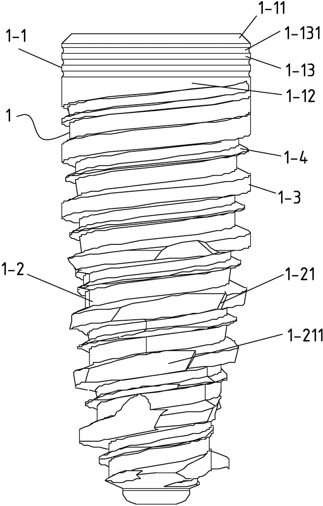
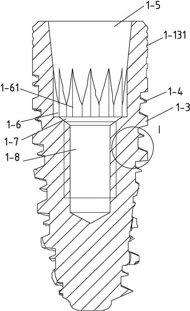
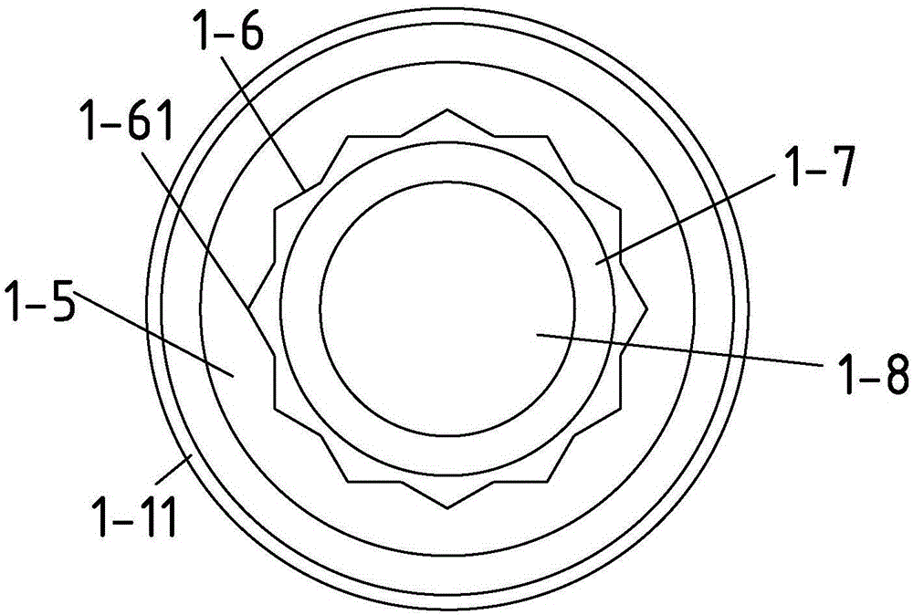
[0041] like Figure 1-Figure 8 As shown, an implant system with a straight abutment is characterized in that it includes an implant 1, a straight abutment 2 and a central bolt 3, and the implant 1 includes a neck 1-1 and a head connected in sequence 1-2, the neck 1-1 is cylindrical, including a chamfered round table 1-11 at the top of the neck 1-1, a threaded section 1-12 connected to the head 1-2 and a The groove section 1-13 between the chamfered round table 1-11 and the threaded section 1-12, the head 1-2 is in the shape of a truncated cone, and its large end is connected to the threaded section 1-12 , the outer surface of the head 1-2 has a thread extending to the thread segment 1-12, the thread includes a main thread 1-3 and a secondary thread 1-3 between the helical intervals of the main thread 1-3 4. The outer diameter of the neck 1-1 is 2-6 mm, the height of the chamfered round table 1-11 is 0.1-0.3 mm, and the height of the implant 1 is 5-15 mm.

[0042] The lead a...


PUM


Abstract

The invention discloses an implant system with a straight base station. The implant system comprises an implant, a straight base station and a central bolt, wherein the implant comprises a neck part and a head part connected in sequence; the neck part is of a cylindrical shape, and comprises a chamfering round table located at a top end of the neck part, a thread section connected with the head part and a groove section located between the chamfering round table and the thread section; the head part is of a frustum shape; a large end of the head part is connected with the thread section; threads extending to the thread section are arranged on an outer surface of the head part; the threads comprise primary threads and secondary threads located between spiral intervals of the primary threads. The implant system provided by the invention adopts a double-thread structure capable of effectively reducing damage to alveolar bone; an outer surface of the implant is coated with a coating for enhancing bone bonding force, so as to contribute to bonding of the implant and the bone; the groove section is adopted to prevent bacteria from entering a part for bonding the implant and the bone, so as to reduce the chance of infection after dental implantation; the outer surface of the central bolt is coated with polytetrafluoroethylene, so that the central bolt and the implant are bonded with the base station more closely and more tightly.

Description

technical field [0001] The invention relates to the technical field of oral medical instruments, in particular to an implant system with a straight abutment. Background technique [0002] With the continuous development of oral implant technology, the "artificial implant" technology has gradually matured and stabilized. Artificial dental implants are to first place a highly biocompatible titanium artificial tooth root into the alveolar for fixation and suture, and after several months to wait for the artificial tooth root to be firmly connected to the bone in the alveolar, the follow-up denture installation is carried out. The artificial tooth root of "artificial implant" is directly combined with the bone, which can provide better supporting force and can chew hard food, so it is very popular. The stability of the implant (root) in the early stage of the artificial dental implant process and the firmness of the connection between the crown, abutment and the implant in the ...

Claims


Application Information

Patent Timeline
Patent Type & Authority Applications(China)
IPC IPC(8): A61C8/00B33Y80/00
CPCA61C8/0022A61C8/0028A61C8/005A61C8/0093B33Y80/00A61C2201/00
Inventor 张蕾张久文蔡俊江李闪宗绪玲彭鹏
Owner DALIAN SANSHENG SCI & TECH DEV
Why Eureka
Eureka Blog
Learn More