MEMS optical switch module with N*N channels

An optical switch and channel technology, applied in the direction of light guide, optics, optical components, etc., can solve the problems of unpractical application, long switching time, large insertion loss, etc., and achieve the effect of light weight, compact structure and low insertion loss

Pending Publication Date: 2017-03-15
NO 34 RES INST OF CHINA ELECTRONICS TECH GRP +2
View PDF7 Cites 6 Cited by
  • Summary
  • Abstract
  • Description
  • Claims
  • Application Information

AI Technical Summary

Problems solved by technology

If the number of channels is increased to N×N according to its structure, the volume will be larger, the power consumption will be too high, the switching time will be too long, and the defects such as large insertion loss will make it impossible for practical application.

Method used


Image

  • MEMS optical switch module with N*N channels
  • MEMS optical switch module with N*N channels
  • MEMS optical switch module with N*N channels

Examples


Embodiment Construction

[0026] The present invention will be further described below in conjunction with the embodiments and accompanying drawings.

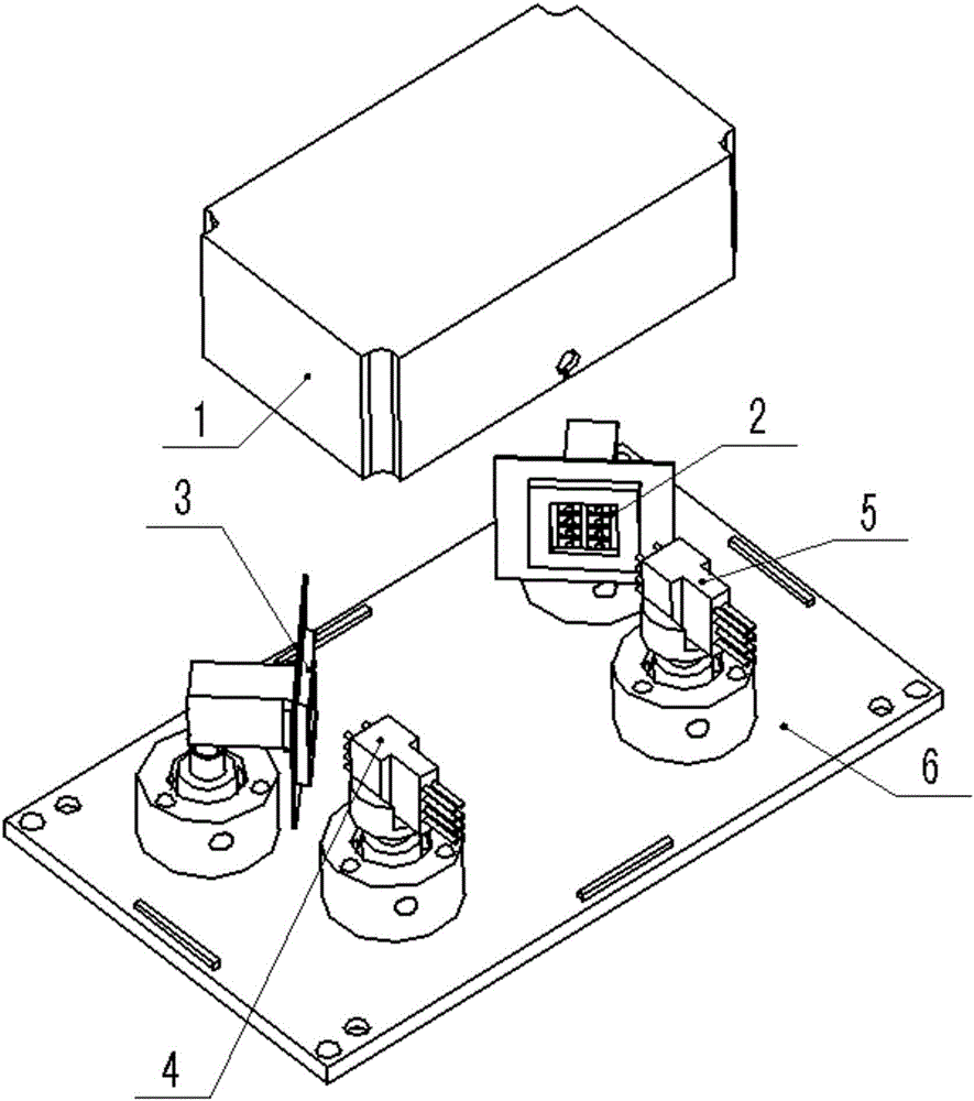
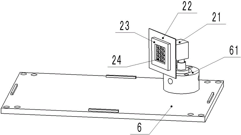
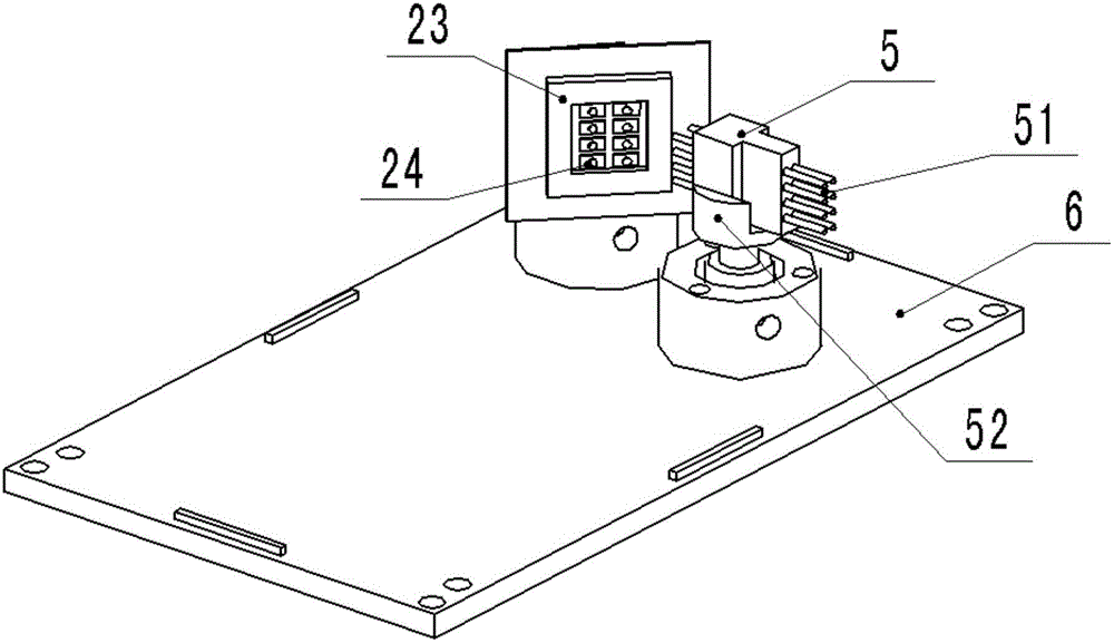
[0027] The MEMS optical switch module embodiment of this N * N channel is the MEMS optical switch module of 8 * 8 channels, such as Figures 1 to 3 As shown, two identical MEMS chips and two identical 8-core collimators are mounted on the same substrate 6 at the same height. The MEMS chip in this example contains 8 micro-mirror mirrors, and the 8 mirrors are arranged in a 2×4 rectangular array on the same plane, which is matched with the 2×4 array of 8-core collimator and 8 optical fibers.

[0028] In this example, two 8-core collimators are parallel to each other, one of which is the first 8-core collimator 5, and its 8 optical fibers are input optical fibers 51, and the 8 lenses matching the input optical fibers 51 are arranged in a plane 2×4 matrix, This plane is perpendicular to the substrate 6; the other is the second 8-core collimator 4, and its ...


PUM


Abstract

The invention relates to an MEMS optical switch module with N*N channels. Two identical MEMS chips and two identical N core collimators are installed at the same height on the same substrate. The lens planes of the two N core collimators are perpendicular to the substrate and parallel to each other. The lens installation planes of the two MEMS chips are perpendicular to the substrate, form an angle of 90 degrees, and face the lens matrix planes of the two N core collimators respectively at a 45-degree angle. Input light imported by an optical fiber of the first N core collimator is reflected when arriving at the lens of the first MEMS chip facing the first N core collimator, is reflected again when arriving at a lens of the second MEMS chip, enters a lens of the second N core collimator, and is output by an output optical fiber. By controlling the lenses of the two MEMS chips, the direction of light can be changed, and all-optical-path switching can be realized. The input and output optical fibers are arranged on the same side of the MEMS chips, and are easy to use. Optical path switching can be carried out at the same time in the multiple channels. Moreover, the MEMS optical switch module has the advantages of fast response, low insertion loss, good stability, compact structure, small size, and low weight.

Description

technical field [0001] The invention relates to the technical fields of optical communication and optical testing, in particular to an N*N channel MEMS optical switch module. Background technique [0002] MEMS (Micro-Electro-Mechanical-Systems) optical switch is a new type of miniaturized optical switch that combines electrical components, mechanical components, and micro-optical components. It is the development of large-capacity all-optical switching network switches. mainstream direction. [0003] The MEMS optical switch is to engrave a number of tiny mirrors on the silicon crystal, and make the micro mirrors mechanically move through static electricity or other control forces, thereby changing the direction of light propagation and realizing the switching function of optical path selection. Compared with other optical switches, MEMS optical switches have obvious advantages. Their switching time is generally on the order of ms. Using IC manufacturing technology, they are...

Claims


Application Information

Patent Timeline
Patent Type & Authority Applications(China)
IPC IPC(8): G02B6/35
CPCG02B6/3518G02B6/3546
Inventor 张策周剑超李流超黄涌李云燕郑安贵唐炳促余志强
Owner NO 34 RES INST OF CHINA ELECTRONICS TECH GRP
Why Eureka
Try Eureka