Multidimensional hydraulic system transient simulation method based on coupling of finite difference method and finite volume method

A finite difference method and finite volume technology, which is applied in special data processing applications, instruments, electrical digital data processing, etc., to achieve the effect of simple method, saving calculation time, and accurate simulation method

Active Publication Date: 2017-03-15
POWER CHINA KUNMING ENG CORP LTD
View PDF7 Cites 17 Cited by
  • Summary
  • Abstract
  • Description
  • Claims
  • Application Information

AI Technical Summary

Problems solved by technology

[0012] Aiming at the deficiencies of the prior art in simulating the unsteady process of complex hydraulic systems, the present invention utilizes the one-dimensional pressurized pipeline unsteady flow control equation, one-dimensional open channel shallow water equation, two-dimensional open channel shallow water equation, and three-dimensional flow equation to propose a Transient simulation method of multi-dimensional hydraulic system based on coupling of finite difference method and finite volume method

Method used


Image

  • Multidimensional hydraulic system transient simulation method based on coupling of finite difference method and finite volume method
  • Multidimensional hydraulic system transient simulation method based on coupling of finite difference method and finite volume method
  • Multidimensional hydraulic system transient simulation method based on coupling of finite difference method and finite volume method

Examples


Embodiment 1

[0049] Embodiment 1: The technical solution of the present invention will be further described below in conjunction with the accompanying drawings.

[0050] The concrete steps of the inventive method are as follows:

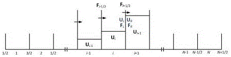
[0051] Step 1. Using the finite difference method-Pressimann space four-point implicit scheme to discretize the one-dimensional unsteady flow control equation of the pressurized pipeline. The governing equations for the unsteady flow in a one-dimensional prism pipe neglecting the slope term are continuity equation (1) and momentum equation (2):

[0052]

[0053]

[0054] Among them, x and t are space and time coordinates, V is the average velocity of the section, H is the head of the piezometric tube, A is the cross-sectional area of ​​the pipeline, f is the Darcy-Weisbach friction coefficient, α is the wave velocity, g is the acceleration of gravity, D is the diameter of the pipe.

[0055] Using a four-point implicit differential scheme in Preissmann spa...

example 1

[0247] Such as Figure 8 As shown, in a hydropower station, in order to measure the pressure in the pipeline, the annular pipe device is often used to measure the pressure pulsation electrically. The reason is that the diameter of the pipeline in the hydropower station is generally large, and the pressure at different points on the same section of the vertical axis may be quite different. The ring device is used to reduce the pressure directly measured at a point on the pipe wall due to pressure fluctuations. Unreliable effects, the average pressure of a section is approximated by the annular communication pipe device, and the reliability of pressure measurement is improved.

[0248] Since the direction of the pipe axis of the ring device is perpendicular to the direction of the water flow in the pipe under test, generally there is no or only a small flow of water in the ring device. A large pressure difference will cause the change of the water flow in the annular pipe, and ...

example 2

[0250] in such as Figure 9 In power stations with long diversion or tailrace tunnels as shown, bifurcated pipes are often used to connect multiple units to the pressure main or tailwater pipeline. On the one hand, at the same time, different units may be in different operating states, for example, some units are in normal operation, while other units are in the process of load shedding, resulting in complex flow patterns in the branch pipes; on the other hand, due to the There are pipes with variable cross-sections in the pipe, and the bifurcation points make the pressure propagation show complex reflection, superposition and other phenomena, which in turn affect the changes of other parameters in the system.

[0251] The coupling method of one-dimensional finite difference method and three-dimensional finite volume method is used to calculate the hydraulic transient process caused by unit load shedding in hydropower stations with bifurcated pipes, such as Figure 9 As shown...


PUM


Abstract

The invention discloses a multidimensional hydraulic system transient simulation method based on the coupling of a finite difference method and a finite volume method, and belongs to the field of simulation of a pipe network system hydraulic transient numerical value. The method adopts a one-dimensional pressure pipeline unsteady flow control equation, a one-dimensional open-channel shallow-water equation, a two-dimensional open-channel shallow-water equation and a three-dimensional flowing equation, and is based on an idea of the coupling of the finite difference method and the finite volume method, the same coupling method is adopted for coupling a one-dimensional pressure pipeline unsteady finite difference method with a one-dimensional pressure pipeline unsteady flow finite volume method, a one-dimensional open-channel unsteady flow finite volume method, a two-dimensional open-channel unsteady flow finite volume method and a three-dimensional complex flowing finite volume method respectively. On one hand, a coupling model utilizes the advantages of a one-dimensional finite difference method that the calculating speed is fast and the processing on boundary conditions is simple in the aspect of simulation of a complex hydraulic system, on the other hand, the coupling model utilizes the characteristic of a multidimensional finite volume method that the accuracy is high during complex flowing calculation, so that the optimal combination of efficiency and accuracy is realized.

Description

technical field [0001] The invention belongs to the field of hydraulic transient numerical simulation of pipe network systems, and in particular relates to a simulation method for an unsteady process of a hydraulic system coupled with a finite difference method and a finite volume method. [0002] technical background [0003] Pipeline pressurized flow and channel shallow water flow are the two most common flows in the hydraulic system of hydropower stations, and can be simulated by one-dimensional, two-dimensional and three-dimensional methods. For unsteady flow in pressurized pipelines, the one-dimensional method is often used for simulation. Among the one-dimensional methods, the characteristic line method and the finite difference method are widely used in the water hammer pressure of the pipeline system because of their easy programming, simple handling of boundary conditions, and high calculation accuracy. simulation. However, the use of finite volume method to simulat...

Claims


Application Information

Patent Timeline
Patent Type & Authority Applications(China)
IPC IPC(8): G06F17/50
CPCG06F30/23
Inventor 王超
Owner POWER CHINA KUNMING ENG CORP LTD
Why Eureka
Try Eureka