Integrated array electron gun and electron beam selective melting rapid formation system

An electron gun, electron beam technology, applied in the direction of cathode ray tube/electron beam tube, electrode device and related components, tube with one or more output electrodes, etc. Problems such as the effective connection of the electron gun area

Active Publication Date: 2017-03-15
XIAN ZHIRONG METAL PRINTING SYST CO LTD
View PDF8 Cites 11 Cited by
  • Summary
  • Abstract
  • Description
  • Claims
  • Application Information

AI Technical Summary

Problems solved by technology

As the deflection angle of the electron beam increases, the quality of the electron beam drops significantly, and electromagnetic calibration can no longer ensure that the beam quality meets the needs of forming
In addition, the beam spot at the edge of the powder bed forming area has a certain deformation when the deflection angle of the electron beam increases, which leads to deviations in the shape of the molten pool and energy distribution, resulting in poor precision and poor forming quality of the formed parts
Using mechanical movement to move the electron gun or powder cylinder will greatly reduce the molding efficiency due to the slow speed of mechanical mov

Method used


Image

  • Integrated array electron gun and electron beam selective melting rapid formation system
  • Integrated array electron gun and electron beam selective melting rapid formation system
  • Integrated array electron gun and electron beam selective melting rapid formation system

Examples


Embodiment Construction

[0026] In order to make the object, technical solution and advantages of the present invention clearer, the present invention will be further described in detail below in conjunction with the accompanying drawings and embodiments. It should be understood that the specific embodiments described here are only used to explain the present invention, not to limit the present invention.

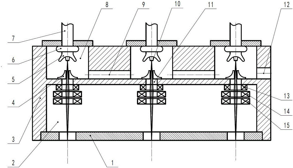
[0027] Such as figure 1 As shown, an integrated array electron gun 20 of the present invention includes an integrated box 3 and a plurality of independent electron beam generating units, and the plurality of electron beam generating units are evenly arranged in the integrated box 3; wherein the integrated box The body 3 is a vacuum box, and is divided into upper and lower parts. The upper part is provided with a plurality of independent vacuum chambers 8 for installing electron beam generating units, and the lower part is an electron beam scanning vacuum chamber 2; each independent vacuum chamber 8...


PUM


Abstract

The invention relates to the technical field of additive manufacturing and processing equipment and especially relates to an integrated array electron gun and an electron beam selective melting rapid formation system. A plurality of electron beam emission units are arranged orderly in an array manner, and each electron beam emission unit is responsible for one region; the electron beam emission units in different array positions are controlled to carry out accurate scanning and forming on different positions of a powder bed, and thus electron beam quality of each electron beam emission unit is ensured; and through effective connection of the regions, under the condition of ensuring part forming precision and quality, the problem that an existing powder bed electron beam selective melting rapid formation device cannot produce large parts due to overlarge electron beam deflection angle is solved, and powder bed electron beam selective melting rapid manufacturing of the large-size parts is realized.

Description

technical field [0001] The invention relates to the technical field of additive manufacturing processing equipment, in particular to an integrated array electron gun and electron beam selective melting rapid prototyping system. Background technique [0002] Additive manufacturing technology is also known as 3D printing or rapid prototyping technology. It is a technology based on digital model files, using materials such as metal powder, wire or bondable plastic, to construct objects by stacking and accumulating layer by layer. Rapid prototyping manufacturing technology is widely used in mold manufacturing, industrial design and other fields, and is gradually being used in the direct manufacturing of some products, especially some high-value applications (such as hip joints or teeth, or some aircraft parts). [0003] Metal parts rapid prototyping manufacturing methods mainly include laser selective sintering (SLS), laser selective melting (SLM), laser coaxial powder feeding ...

Claims


Application Information

Patent Timeline
IPC IPC(8): H01J29/48H01J29/50H01J31/06
CPCH01J29/488H01J29/503H01J31/06
Inventor 郭光耀
Owner XIAN ZHIRONG METAL PRINTING SYST CO LTD
Why Eureka
Try Eureka