
Airborne energy storage reverse wireless power supply system and power supply method for UAV

A wireless power supply and unmanned aerial vehicle technology, applied in the direction of circuit devices, electrical components, etc., can solve the problems of beam energy loss, power supply facilities can not reach the equipment, etc., to achieve the effect of convenient use, good controllability, and low maintenance cost

Active Publication Date: 2019-08-02
南京中科聚能科技有限公司
View PDF3 Cites 0 Cited by
  • Summary
  • Abstract
  • Description
  • Claims
  • Application Information

AI Technical Summary

Problems solved by technology

The laser has strong directionality and energy concentration, and there is no risk of interfering with communication satellites, but obstacles will affect the energy exchange between the laser and the receiving device, and the beam energy will be partially lost during transmission
[0006] With the continuous advent of various high-tech products, small-power devices such as infrared cameras and temporary communication base stations are installed on the top of the mountain or in the woods. There is a large demand for power supply, and normal power supply facilities often cannot reach the location of the equipment.

Method used


Image

  • Airborne energy storage reverse wireless power supply system and power supply method for UAV
  • Airborne energy storage reverse wireless power supply system and power supply method for UAV
  • Airborne energy storage reverse wireless power supply system and power supply method for UAV

Examples


Embodiment Construction

[0024] Embodiments of the present invention will be described in detail below in conjunction with the accompanying drawings.

[0025] Examples of the described embodiments are shown in the drawings, wherein like or similar reference numerals designate like or similar elements or elements having the same or similar functions throughout. The embodiments described below by referring to the figures are exemplary only for explaining the present invention and should not be construed as limiting the present invention.

[0026] The following disclosure provides many different embodiments or examples for implementing different structures of the present invention. To simplify the disclosure of the present invention, components and arrangements of specific examples are described below. They are examples only and are not intended to limit the invention. Furthermore, the present invention may repeat reference numerals and / or letters in different instances. This repetition is for the pur...


PUM


Abstract

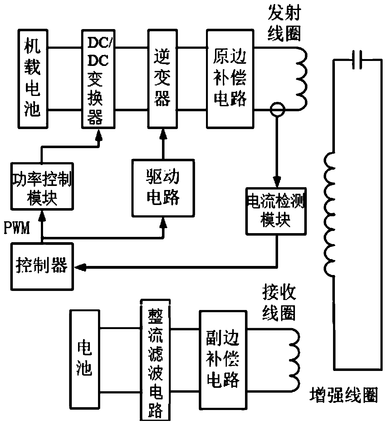
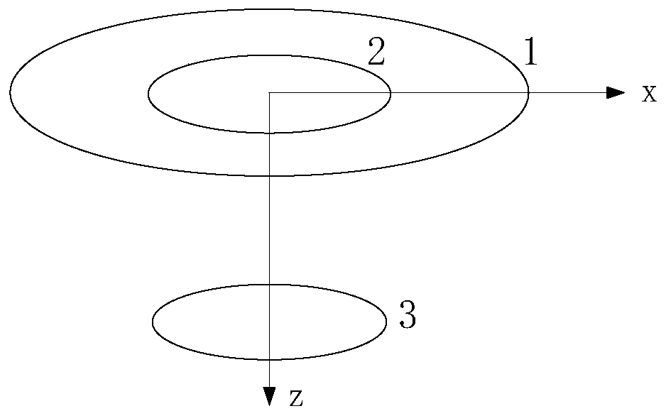
The invention relates to the technical field of wireless power transmission, in particular to an airborne energy storage reverse wireless power supply system and power supply method of an unmanned aerial vehicle. The reverse wireless power supply system comprises the unmanned aerial vehicle, low-power power receiving equipment, a transmitting unit and a receiving unit, wherein the transmitting unit is arranged on the unmanned aerial vehicle; the receiving unit is arranged on the low-power power receiving equipment; the transmitting unit comprises an airborne battery, a DC / DC converter, an inverter, a primary side compensation circuit, a transmitting coil, an intensifier coil, a current detection module connected with a controller and the transmitting coil, a drive circuit connected with the controller and the inverter, and a power control module connected with the controller and the DC / DC converter; the airborne battery, the DC / DC converter, the inverter, the primary side compensation circuit, the transmitting coil and the intensifier coil are sequentially connected; the receiving unit comprises a receiving coil, a secondary side compensation circuit, a rectifier and filter circuit and a battery which are sequentially connected; the intensifier coil and the transmitting coil are concentric and are located in the same plane; and the transmitting coil and the receiving coil are parallel and coaxial. According to the system, the middle-long range transmission efficiency is strengthened; and a wireless charging system has higher robustness and relatively low environmental electromagnetic radiation characteristics.

Description

technical field [0001] The invention belongs to the technical field of wireless energy transmission, and in particular relates to an onboard energy storage reverse wireless power supply system and a power supply method of an unmanned aerial vehicle. Background technique [0002] Wireless power supply technology mainly realizes non-contact power transmission through electromagnetic induction, electromagnetic resonance, radio frequency, microwave and laser. According to the different power supply distances of wireless power transmission in space, the forms of wireless power transmission can be divided into three categories: short-range, medium-range and long-range. [0003] Among them, the one realized by electromagnetic induction power transfer technology (ICPT) belongs to short-range transmission. ICPT mainly uses a magnetic field as the medium, uses transformer coupling, and induces current through the primary and secondary coils. Electric energy can be transmitted through...

Claims


Application Information

Patent Timeline
Patent Type & Authority Patents(China)
IPC IPC(8): H02J50/10H02J50/50H02J50/80
Inventor 蔡昌松王军华李国城刘士齐胡妹林方支剑
Owner 南京中科聚能科技有限公司
Learn More