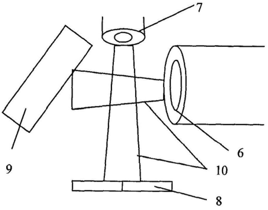
A coating method for thin film of laser gyroscope reflector
A technology of laser gyroscope and reflector, which is applied in sputtering coating, Sagnac effect gyroscope, mirror, etc., can solve the problems of large absorption and scattering, and achieve the effect of low cost, simple operation and good economy
Inactive Publication Date: 2014-04-23
FLIGHT AUTOMATIC CONTROL RES INST
View PDF0 Cites 3 Cited by
- Summary
- Abstract
- Description
- Claims
- Application Information
AI Technical Summary
Problems solved by technology
There are problems of large absorption and scattering when coating thin films on top. The invention provides an ultra-smooth laser gyro
Method used
View moreImage
Smart ImageViewing Examples
Examples
Embodiment Construction
[0032] Step 7: step 4 to step 6 is carried out in a loop until all the layers are plated.
Login to View More PUM
 Abstract
The invention relates to a method for coating a thin film of a laser gyro reflector, in particular to a method for coating a high-reflection film system on an ultra-smooth substrate that does not reach the Angstrom level. When the coating method of laser gyroscope mirror film of the present invention is by adopting ion beam sputtering deposition technology to prepare multilayer oxide optical film, every high refractive index layer (such as odd numbers such as 1, 3, 5 in the high reflection film system) is plated The layer is a high refractive index layer), pause for a period of time, and then use the oxygen-argon mixed ion beam to treat the coating surface, and then pause for a period of time, then proceed to the next layer of plating, and cycle in turn until all the layers are plated. The coating method of the thin film of the laser gyroscope reflector of the invention helps to reduce the absorption loss and volume scattering loss of the film layer, thereby preparing a high-quality and low-loss reflector on the ultra-smooth substrate that does not reach the Angstrom level. At the same time, it has the characteristics of simple operation, low cost and good economy, and has high practical application value.
Description
A kind of coating method of laser gyroscope reflector thin film Technical field The present invention relates to a kind of coating method of laser gyroscope reflector thin film, especially about a kind of A coating method for coating a high-reflection film system on a super-smooth substrate. Background technique Reflector is one of core device of laser gyroscope, the quality of its performance directly affects the key technology of laser gyroscope technical indicators. Through the control of several mirrors, the laser can be confined in the cavity to form a ring laser, so the laser gyro is required The reflector in the screw minimizes the loss of the laser, and minimizes the influence of the reflector itself on the ring laser. For this, need Develop mirrors with low loss and high reflection performance. At present, ion beam sputtering deposition coating technology is the first-selected technology of coating high-quality optical thin film, and is also the most impor...
Claims
Login to View More Application Information
Patent Timeline
 Patent Type & Authority Patents(China)
IPC IPC(8): C23C14/46G02B5/08G01C19/64
Inventor 苏宇刘希强薛青云
Owner FLIGHT AUTOMATIC CONTROL RES INST
Features
- R&D
- Intellectual Property
- Life Sciences
- Materials
- Tech Scout
- Unparalleled Data Quality
- Higher Quality Content
- 60% Fewer Hallucinations
Learn More Browse by: Latest US Patents, China's latest patents, Technical Efficacy Thesaurus, Application Domain, Technology Topic, Popular Technical Reports.
© 2025 PatSnap. All rights reserved.Legal|Privacy policy|Modern Slavery Act Transparency Statement|Sitemap|About US| Contact US: help@patsnap.com


