
Multi-baffle counterflow photo-catalytic reaction device

A catalytic reaction, countercurrent light technology, applied in the detailed information of chemical/physical/physical chemical reactors, chemical instruments and methods, chemical/physical processes, etc., can solve the problem that the contact area between the reaction solution and the catalyst is not much improved, Can not fully mix the solid-liquid two phases, can not be fully stirred, etc., to achieve the effect of less catalyst consumption, easy separation, and high utilization of light energy

Active Publication Date: 2017-03-22
INNER MONGOLIA NORMAL UNIVERSITY
View PDF5 Cites 3 Cited by
  • Summary
  • Abstract
  • Description
  • Claims
  • Application Information

AI Technical Summary

Problems solved by technology

[0004] At present, there are many liquid-solid phase photocatalytic reactors that apply fluidization process in photocatalytic reaction equipment, but the photocatalytic reactors designed by them all use the convective principle of solid-liquid phase in fluidization for photocatalysis. It cannot fully mix the solid-liquid two phases, such as patent No. 201510132687.9, which is named "A Photocatalytic Water Splitting Hydrogen Production Device", which uses traditional impeller stirring, which not only cannot fully stir, but also wastes energy
Patent No. 200420054774.4, titled "Fluidized Bed Photocatalytic Water Oxidation Reactor", which applies the traditional fluidization principle, and at the same time passes the gas-liquid-solid three-phase into the reaction. Although this is in line with the fluidization principle, it is for The contact area between the reaction solution and the catalyst does not increase much

Method used


Image

  • Multi-baffle counterflow photo-catalytic reaction device

Examples


Embodiment Construction

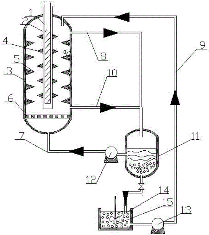
[0020] Such as figure 1 As shown, the action process of the device is as follows,

[0021] S1 closes the valve at the bottom of the catalyst settling tank 11, and adds the reaction liquid, and when the liquid level of the reaction liquid exceeds the reaction liquid inlet 7, open the pump 12. When the reaction liquid in the cylindrical-conical reaction tower 3 can flow back to the catalyst settling tank 11 from the reaction liquid outlet 8, stop adding the reaction liquid to realize liquid phase circulation.

[0022] S2 turns on light source 1.

[0023] S3 adds solid catalyst from the upper part of the cylindrical conical reaction tower 3, and the static mixing through the multi-stage baffle can fully contact with the reaction solution. 11 The bottom settles, open the valve at the bottom of the catalyst settling tank 11, and add a certain amount of reaction solution.

[0024] S4 When the catalyst suspension liquid level exceeds the blade agitator 14, open the blade agitator...


PUM


Abstract

The invention discloses a multi-baffle counterflow photo-catalytic reaction device. A light source is fixedly arranged on the central position of a cylindrical tapered reactor; a light source outer isolating sleeve is matched with the light source; a fixed tapered baffle on the isolating sleeve is distributed on the light source outer isolating sleeve; a tapered baffle of a fixed tower wall is distributed on the cylindrical tapered reaction tower; a distributing plate is fixedly arranged on the bent position of the cylindrical tapered reaction tower; a reaction liquid inlet is connected with the bottom of the cylindrical tapered reaction tower; a reaction liquid outlet is connected with the top of the cylindrical tapered reaction tower; the reaction liquid inlet is connected with the upper part of a catalyst settling tank; a pump a is used for conveying a reaction liquid; the reaction liquid outlet and the catalyst turbid liquid outlet enter the catalyst settling tank; the bottom of the catalyst settling tank is matched with a catalyst turbid liquid storage slot; a blade stirrer is fixedly arranged on the center of the catalyst turbid liquid storage slot; the catalyst turbid liquid inlet is connected with the bottom of the catalyst turbid liquid storage slot; and a pump b is used for conveying the catalyst turbid liquid.

Description

technical field [0001] The invention relates to a multi-baffle counterflow photocatalytic reaction device, in particular to a static distribution fluidized photocatalytic reaction device. Background technique [0002] Since Japanese scientist Akira Fujishima discovered that titanium oxide single crystals can decompose water under light conditions to produce hydrogen and oxygen in the 1970s, photocatalytic technology has become the focus of research by many researchers. The principle of photocatalytic technology is based on TiO 2 , ZnO, ZnS, CdS, PbS, WO 3 Such semiconductor materials as photocatalysts, through the excitation of ultraviolet light source or near ultraviolet light source, make positively charged holes on the surface of semiconductor photocatalyst particles, thus triggering a series of redox reactions. [0003] Photocatalytic technology has important applications in various countries and fields in the world: photocatalyst preparation research, photocatalyst re...

Claims


Application Information

Patent Timeline
IPC IPC(8): B01J19/12B01J19/00B01J8/18B01J8/20
CPCB01J8/18B01J8/1881B01J8/20B01J19/0053B01J19/006B01J19/122B01J2208/00769B01J2208/0084B01J2219/00765B01J2219/0869B01J2219/089
Inventor 徐爱菊王奖贾美林照日格图侯海元
Owner INNER MONGOLIA NORMAL UNIVERSITY
Learn More