Eureka AIR delivers breakthrough ideas for toughest innovation challenges, trusted by R&D personnel around the world.

Laser surface strengthening machining device and method for plane type valve sealing surface

A valve sealing and surface strengthening technology, which is applied in laser welding equipment, metal processing equipment, welding equipment, etc., can solve the problems of high energy consumption, large dilution rate, and high strengthening cost

Inactive Publication Date: 2017-03-22
浙江久恒光电科技有限公司
View PDF10 Cites 3 Cited by
  • Summary
  • Abstract
  • Description
  • Claims
  • Application Information

AI Technical Summary

Problems solved by technology

The first three surface modification technologies all need to use flame, electric arc, and plasma as heat sources, and their common disadvantages are: high energy consumption, easy deformation, easy cracking, and large dilution rate
However, the equipment is expensive, and the strengthening cost is very high. Due to the limitation of price and cladding process materials, laser strengthening technology cannot be applied industrially. A special equipment for laser surface strengthening of the sealing surface of planar valves is developed to reduce the cost. It is of great significance to reduce the cost of laser strengthening of the sealing surface of the valve and realize the low-cost mass production and industrial application of the sealing surface of planar valves.

Method used


Image

  • Laser surface strengthening machining device and method for plane type valve sealing surface
  • Laser surface strengthening machining device and method for plane type valve sealing surface
  • Laser surface strengthening machining device and method for plane type valve sealing surface

Examples


Embodiment Construction

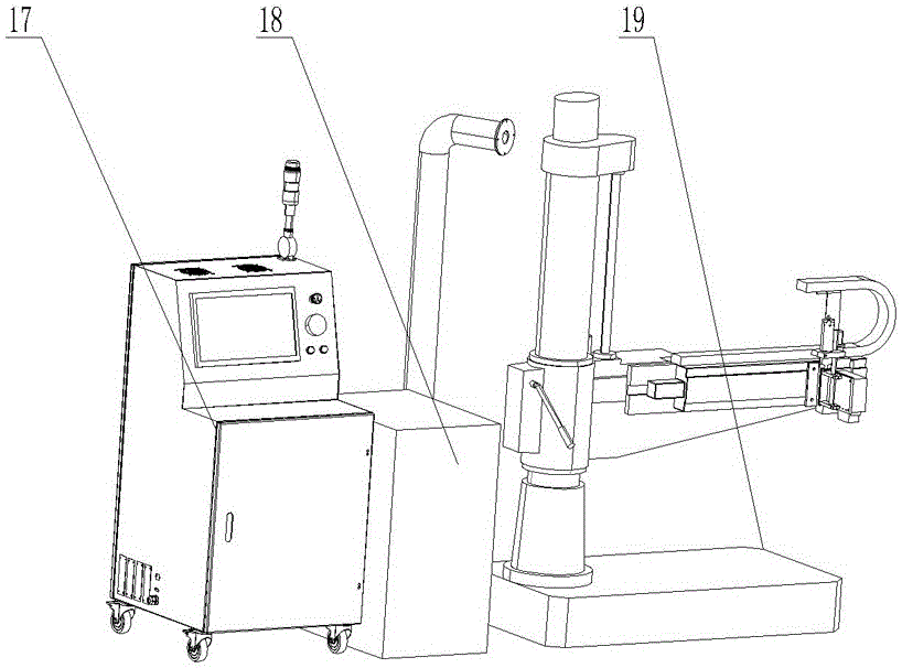
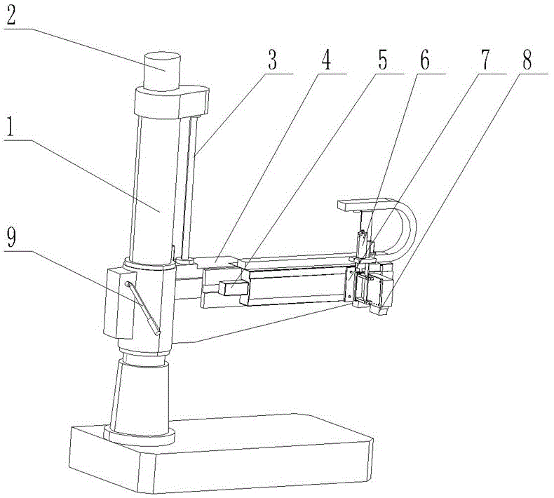
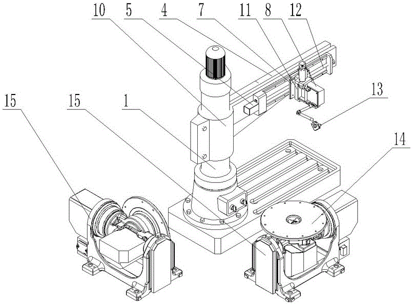
[0028] Referring to the accompanying drawings, this laser surface strengthening processing equipment for the sealing surface of flat valves includes a control cabinet 17, a powder feeding device 18 and a laser processing device 19, the control cabinet 17 is provided with a controller, and the laser processing The device 19 has a column, and the column 1 is equipped with a rocker arm 4 that can rotate in all directions through a shaft sleeve 10, wherein the rocker arm 4 can be rotated manually or electrically; A fastening bolt 9 is arranged on the sleeve 10, and when the rocking arm 4 is manually rotated to a certain position, the bolt 4 is tightened to fix the rocking arm 4. When electric rotation, be that the sleeve 10 of rocking arm 4 on described column 1 is connected with a driving device transmission transmission, this driving device can be motor, utilizes the rotating shaft transmission connection gear of motor, in the sleeve of rocking arm A ring gear with external teet...


PUM


Abstract

The invention discloses a laser surface strengthening machining device for a plane type valve sealing surface. The machining device is characterized by comprising a control cabinet, a powder feeding device and a laser machining device; a controller is arranged in the control cabinet; the laser machining device is provided with a stand column sleeved with a rocker arm capable of rotating in all directions; a first sliding platform capable of moving horizontally is arranged on the rocker arm; a second sliding platform capable of moving vertically is mounted on the first sliding platform; a laser head and a powder feeding head are arranged on the second sliding platform; the powder feeding head is connected with the powder feeding device; the rocker arm moves vertically on the stand column; the vertical movement of the rocker arm and the vertical movement of the second sliding platform form a double-Z-axis structure; and machining stations are arranged on the periphery of the stand column. The double-Z-axis structure is adopted, the device has the high precision for adjusting the machining position of a machined piece, and the machining process and the preparation process of the device do not interfere with each other, so that the device has the advantages that the machining precision is high, the quality of a machined layer is well controlled, the device is convenient and simple to operate and the like. The invention further discloses a machining method.

Description

technical field [0001] The invention relates to equipment for laser surface strengthening processing, in particular to equipment for laser cladding or quenching on the sealing surface of a flat valve. Background technique [0002] Laser surface strengthening technology is to make the desired physical and chemical changes on the surface of the material through the interaction between the laser and the material. When the high power density focused laser beam acts on the metal surface, the metal surface absorbs the laser energy and heats up at a very high speed (up to 10 10 K / s) is heated, melted and even gasified. Since the thermal effect is only concentrated in a very thin local area of ​​the material surface, a very high temperature gradient will be formed between the heated surface layer and the metal substrate. When the laser is off, the good thermal conductivity of the metal will cause the surface to 4 -10 8 Cooling at a rate of K / s. Laser surface treatment has the ...

Claims


Application Information

Patent Timeline
IPC IPC(8): B23K26/342B23K26/352B22F3/105
CPCB22F3/105B23K26/342B23K26/352Y02P10/25
Inventor 吴旭浩徐昶吴斌陈开宇杨明烨
Owner 浙江久恒光电科技有限公司
Why Eureka
Eureka Blog
Learn More