High-performance tripod head

A high-performance, pan-tilt technology, applied in the field of high-performance pan-tilt, can solve the problems such as inability to effectively eliminate jitter, large torque fluctuation of pan-tilt motor, affecting pan-tilt imaging effect, etc., to improve imaging effect and high operating efficiency. , start the smooth effect

Inactive Publication Date: 2017-03-22
ONCE TOP MOTOR MFG
View PDF8 Cites 8 Cited by
  • Summary
  • Abstract
  • Description
  • Claims
  • Application Information

AI Technical Summary

Problems solved by technology

For this reason, the main purpose of the present invention is to provide a kind of high-performance pan-tilt motor with stable start and operation, aiming to solve the problem that the traditional pan-tilt motor has large torque fluctuations, can not effectively eliminate jitter, and affects the imaging effect of the pan-tilt

Method used


Image

  • High-performance tripod head
  • High-performance tripod head
  • High-performance tripod head

Examples


Embodiment 1

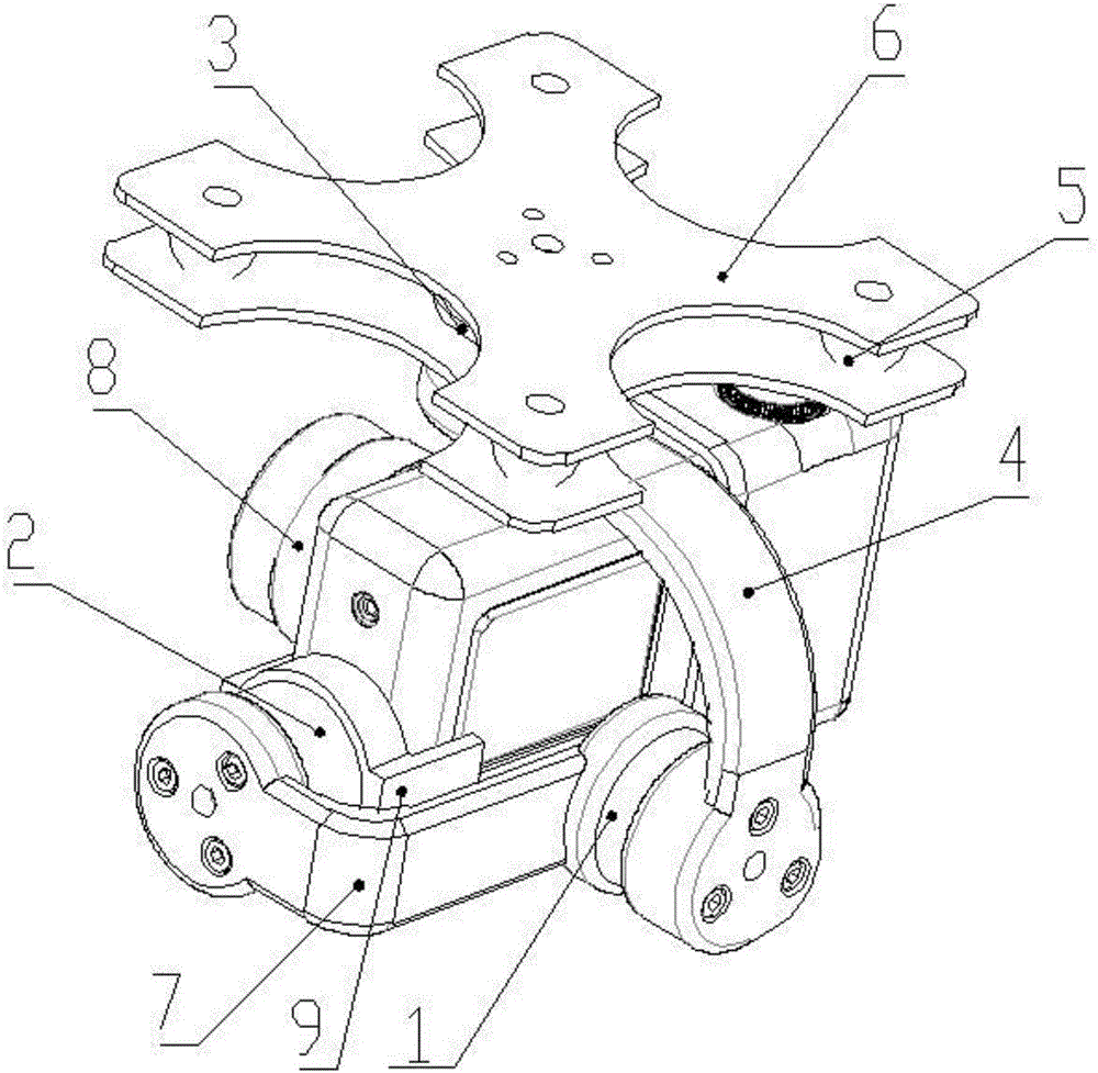
[0051] refer to Figure 1 ~ Figure 3 , the high-performance pan-tilt provided in this embodiment is used for aerial photography, and the high-performance pan-tilt includes a pan-tilt motor 100, a pan-tilt bracket 6 connected to one end of the pan-tilt motor 100 and a camera 8 connected to the other end of the pan-tilt motor 100;

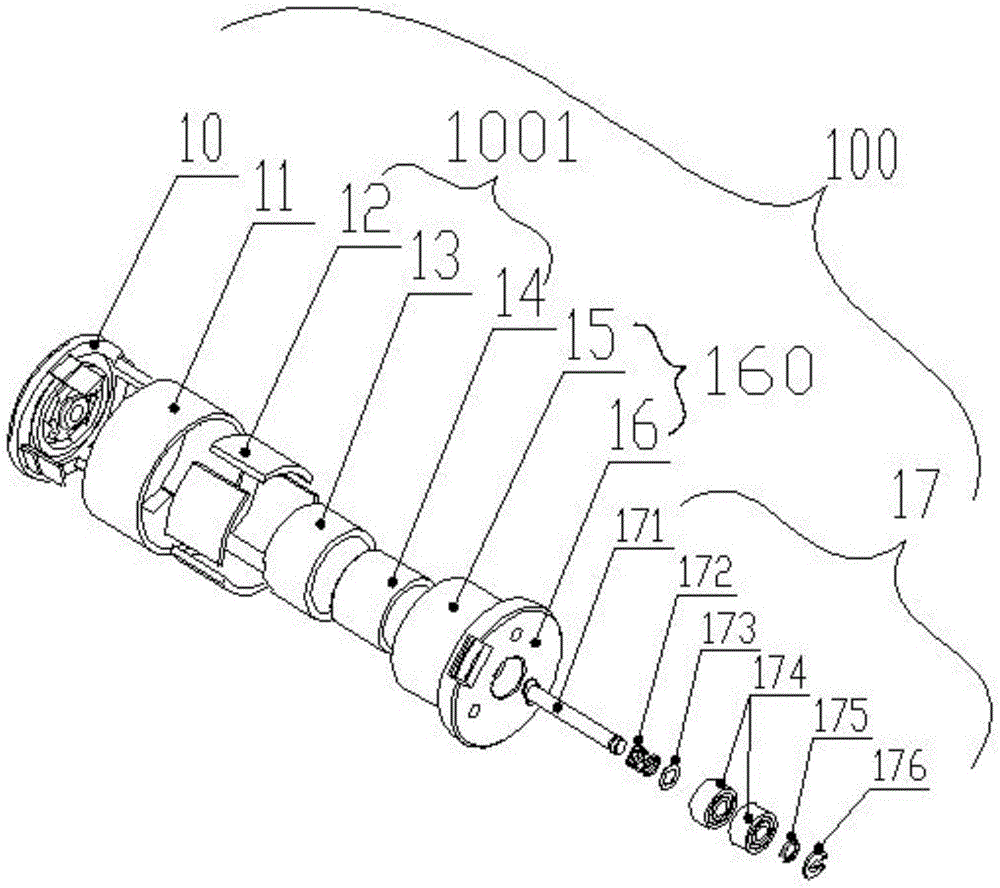
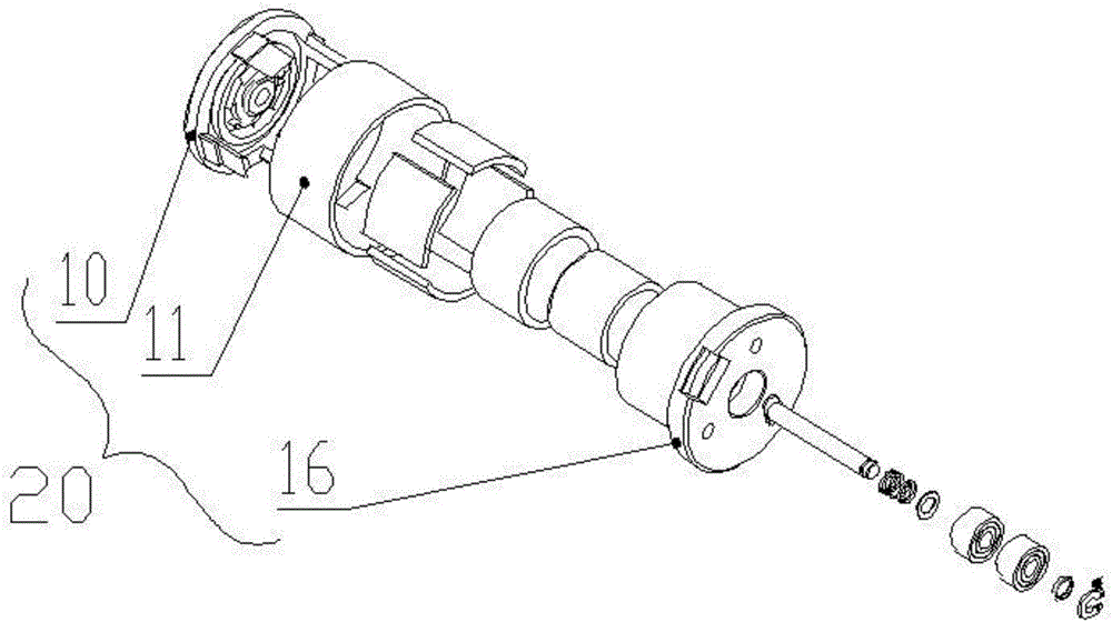
[0052]The pan / tilt motor 100 includes a casing 20, a stator assembly 160 disposed in the casing 20, a rotor assembly 1001 coaxially arranged with the stator assembly 160, and a shaft system passing through the center of the stator assembly 160 and the rotor assembly 1001 from one end of the casing 20 Part 17;

[0053] Wherein, the casing 20 includes a front cover 10 and an outer cover 11 connected to the front cover 10;

[0054] The rotor assemblies 1001 are all ring-shaped, and the rotor assembly 1001 includes: an outer magnet 12 arranged close to the inner wall of the outer cover 11, an inner magnet 13 arranged in the inner ring of the outer magne...

Embodiment 2

[0061] refer to Figure 2 ~ Figure 4 The difference from the above embodiment is that, preferably, the center of the front cover 10 is provided with a groove 102, and the outer ring of the groove 102 is provided with an inner yoke mounting hole 103, an outer magnet slot 101 and an outer surface of the front cover 10. There are claws 104 between the diameters;

[0062] Among them, the groove 102 is connected with one end of the shafting part 17, the inner yoke installation hole 103 is interference fit with the inner yoke 14, the claw 104 is connected with the groove 111 provided on the outer cover 11, and the claw 104 is connected with the groove 111 Fastened by glue, the outer magnet 12 is arranged between two adjacent jaws 104 and fastened by glue.

[0063] The inner wall of the outer cover 11 has a slot 111 to cooperate with the claw 104 of the front cover 10, and further tighten the connection by gluing, which can effectively prevent loosening and circumferential slipping....

Embodiment 3

[0073] like figure 1 As shown, the difference from the above-mentioned embodiment is that, preferably, the pan-tilt bracket 6 is a composite structure, and shock-absorbing balls 5 are provided on the corners of the pan-tilt bracket 6 .

[0074] Preferably, there are three pan-tilt motors 100, which are the pan-axis pan-tilt motor 3 arranged at the top of the camera 8, the pitch-axis pan-tilt motor 2 arranged on the side of the camera 8, and the roll-axis pan-tilt motor arranged at the rear end of the camera 8. motor 1;

[0075] One end of the pitch axis gimbal motor 2 is connected to the camera 8 through the camera mount 9, and the other end is connected to the roll axis gimbal motor 1 through the second connecting arm 7;

[0076] The pan-tilt motor 1 of the roll axis is connected to the pan-tilt motor 3 through the first connecting arm 4, one end of the pan-tilt motor 3 is connected to the first connecting arm 4, and the other end of the pan-tilt motor 3 is connected to the ...


PUM


Abstract

The invention discloses a high-performance tripod head. The high-performance tripod head comprises a tripod head motor, a tripod head support connected with one end of the tripod head motor, and a camera connected with the other end of the tripod head motor. The tripod head motor comprises a motor shell, a stator assembly arranged in the motor shell, a rotor assembly and shafting parts. The rotor assembly and the stator assembly are arranged coaxially. The shafting parts penetrate through the centers of the stator assembly and the rotor assembly from one end of the motor shell. The motor shell comprises a front cover and an outer housing connected with the front cover. The rotor assembly is annular and comprises an outer magnet attached to the inner wall of the outer housing, an inner magnet arranged in an inner ring of the outer magnet, and an inner magnet yoke arranged in an inner ring of the inner magnet. The outer magnet is of a sheet structure. The outer magnet and the inner magnet are arranged correspondingly, so that magnetomotive force forms a series connection form. The number of magnetic pole pairs of the outer magnet and the inner magnet is at least one. The stator assembly is arranged between the outer magnet and the inner magnet. The problems that torque ripple of a traditional tripod head motor is large, shake cannot be eliminated effectively, and the tripod head imaging effect is influenced are solved.

Description

technical field [0001] The invention relates to the technical field of aircraft power devices, in particular to a high-performance cloud platform. Background technique [0002] The pan / tilt is a supporting device for installing and fixing the camera, and it is divided into two types: fixed and electric pan / tilt. [0003] Among them, the fixed pan / tilt is suitable for the situation where the monitoring range is not large. After installing the camera on the fixed pan / tilt, you can adjust the horizontal and pitch angles of the camera. After reaching the best working posture, you only need to lock the adjustment mechanism. [0004] The electric pan / tilt is suitable for scanning and monitoring a large area, and it can expand the monitoring range of the camera. The high-speed attitude of the electric pan / tilt is realized by the executive motor, and the motor receives the signal from the controller to accurately run and position. Under the action of the control signal, the camera...

Claims


Application Information

Patent Timeline
Patent Type & Authority Applications(China)
IPC IPC(8): B64D47/08H02K1/27H02K5/16H02K5/24
CPCH02K1/2793H02K5/161H02K5/24B64D47/08B64U2101/30
Inventor 马开宏张子茂
Owner ONCE TOP MOTOR MFG
Why Eureka
Try Eureka