
Plunger type coal ash pressurized conveying device

A conveying device and plunger type technology, which is applied in the field of plunger type pulverized coal pressurized conveying devices, can solve the problems of high valve sealing and pressure resistance requirements of pulverized coal pipelines, low efficiency in the conveying process, and inability to continuously adjust, etc. Go to automatic control, light weight, reduce the effect of pulverized coal pipeline

Pending Publication Date: 2017-03-22
CHANGZHENG ENG
View PDF1 Cites 1 Cited by
  • Summary
  • Abstract
  • Description
  • Claims
  • Application Information

AI Technical Summary

Problems solved by technology

[0006] In order to solve the problem that current pulverized coal pressurized conveying technology emits a large amount of inert gas, which causes serious environmental pollution; the conveying process is inefficient, and although the feeding amount can be stable and controllable, it cannot be adjusted continuously; high-pressure equipment with large volume and high cost is required; High energy consumption, high requirements for the sealing and pressure resistance of pulverized coal pipeline valves, etc., the embodiment of the present invention provides a plunger type pulverized coal pressurized conveying device, which increases the pressure of pulverized coal through the movement of the piston parts, without the need for inert gas Participate in the transportation, and can carry out continuous transportation of pulverized coal at the same time, which has the advantage of low energy consumption

Method used


Image

  • Plunger type coal ash pressurized conveying device
  • Plunger type coal ash pressurized conveying device

Examples


Embodiment Construction

[0036] In order to make the technical problems, technical solutions and advantages to be solved by the present invention clearer, the following will describe in detail with reference to the drawings and specific embodiments.

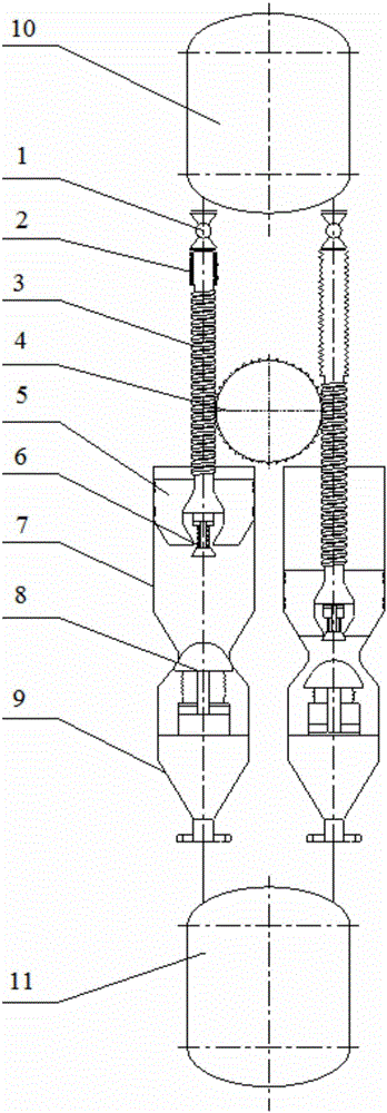
[0037] like figure 1 A schematic structural diagram of a plunger-type pulverized coal pressurized conveying device provided by an embodiment of the present invention, as shown in figure 1 As shown in , the device includes: a driving part 4 and two conveying passages arranged in parallel; the upper and lower ends of the conveying passage are respectively connected with the atmospheric pressure storage tank 10 and the pulverized coal feeding tank 11; the conveying passage includes a normal Press feed valve 1, retractable pulverized coal conveying pipeline 2, worm pulverized coal conveying pipeline 3, piston part 5, pulverized coal feed valve 6, pulverized coal conveying chamber 7, pulverized coal discharge valve 8, and discharge section 9; Among them, the...


PUM


Abstract

The invention provides a plunger type coal ash pressurized conveying device and belongs to the technical field of coal chemical engineering for solving the problems that an existing coal ash pressurized conveying technology is low and the like. The device provided by the invention comprises a driving part and two conveying channels which are arranged in parallel; the upper and lower ends of each of the conveying channels are connected to a constant pressure storage tank and a coal ash feeding tank, respectively; a constant pressure feeding valve is arranged at the upper end of each of the conveying channels, the lower end outlet of the constant pressure feeding valve is connected to a stretchable coal ash conveying pipeline, the lower end of the stretchable coal ash conveying pipeline is connected to a worm coal ash conveying pipeline, the lower end of the worm coal ash conveying pipeline is connected to a coal as feeding valve in a piston part, the piston part is located in a coal ash conveying cavity, the lower end output port of the coal ash conveying cavity is connected to the upper end inlet of a blanking section, the lower end outlet of the blanking section is connected to a coal ash feeding tank, and a coal ash blanking valve is arranged at the connection of the coal ash conveying cavity and the blanking section; the driving part is used for driving the piston rod to do a reciprocating rectilinear movement. The device has the characteristic of being low in energy consumption.

Description

technical field [0001] The invention relates to the technical field of coal chemical industry, in particular to a plunger type pulverized coal pressure conveying device. Background technique [0002] The pressurized conveying process of powder is involved in many fields such as coal chemical industry, metallurgy, and food processing. Coal gasification, especially pulverized coal pressurized gasification is a clean coal utilization technology, which has been developed rapidly in recent years and has been used more and more widely. Pulverized coal pressurized conveying technology is an indispensable technical link in pulverized coal pressurized gasification technology. Pulverized coal pressurized conveying technology is to increase dry coal powder from normal pressure to a specific high pressure, so as to realize the combustion and gasification of pulverized coal under high pressure. [0003] The pulverized coal pressurized conveying technology currently used in industry is ...

Claims


Application Information

Patent Timeline
Patent Type & Authority Applications(China)
IPC IPC(8): B65G53/08B65G53/46B65G53/48
CPCB65G53/08B65G53/4683B65G53/48
Inventor 姜从斌王明坤霍耿磊章刚甘晓雁商贵信马超王卉
Owner CHANGZHENG ENG
Learn More