Range hood with double series fans

A technology of range hoods and models, which is applied in the direction of removing oil fumes, machines/engines, mechanical equipment, etc. It can solve the problems of large fluid resistance, large installation space, and high noise, and achieves reduced wind resistance, increased air intake area, Noise reduction effect

Inactive Publication Date: 2017-03-22
NINGBO FOTILE KITCHEN WARE CO LTD
View PDF10 Cites 2 Cited by
  • Summary
  • Abstract
  • Description
  • Claims
  • Application Information

AI Technical Summary

Problems solved by technology

However, in this document, the primary fan and the secondary fan are in the same vertical direction, and a long connecting pipe is required from the air outlet of the primary fan to the air inlet of the secondary fan. It is very large, and at the same time, it requires more installation space in the vertical direction.

Method used


Image

  • Range hood with double series fans
  • Range hood with double series fans
  • Range hood with double series fans

Examples


Embodiment 1

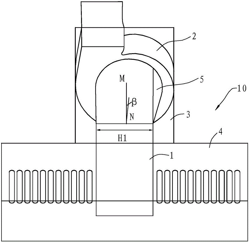
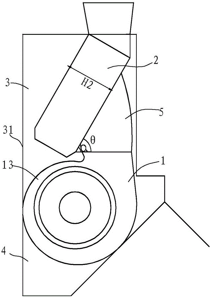
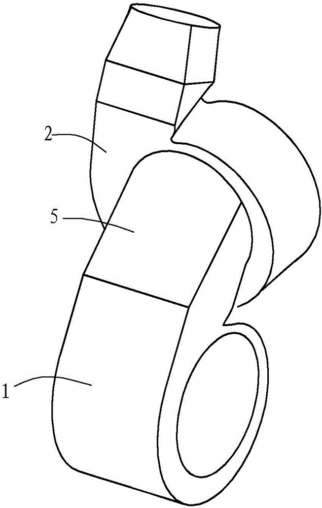
[0029] Example 1, such as figure 1 , figure 2 and image 3 As shown, the tandem double-fan type range hood in this embodiment includes a casing 10 and a first-stage centrifugal fan 1 and a second-stage centrifugal fan 2 arranged in the casing 10, and the casing 10 includes a fan casing 3 and a set The smoke collecting hood 4 at the lower end of the fan cover, the back side of the fan cover 3 is a flat installation surface, and the air inlet of the secondary centrifugal fan 2 is oriented perpendicular to the installation surface 31 . The fume collecting hood 4 is arranged horizontally, and the first-stage centrifugal fan 1 is located in the middle of the fume collecting hood 4 .

[0030] The casing 10 has an oil fume inlet at the lower end and an oil fume outlet at the upper end. The air inlet of the first-stage centrifugal fan 1 communicates with the oil fume inlet, the air outlet of the first-stage centrifugal fan 1 communicates with the air inlet of the second-stage centr...

Embodiment 2

[0037] Example 2, such as Figure 4 , Figure 5 , Figure 6 and Figure 7 As shown, in this embodiment, the air outlet of the primary centrifugal fan 1 is connected to the air inlet of the secondary centrifugal fan 2 through the diffuser section 5a. The diffuser section 5a is integrated with the volute of the first-stage centrifugal fan 1 . In order to maintain the centering and airtightness, a mounting plate is designed at the rear end of the diffuser section 5a. The mounting plate can be fixed with the sealing plate 31 and the sealing plate 32 on both sides of the air inlet end face of the secondary centrifugal fan 2. The sealing plate 31 and the sealing plate The plate 32 plays the role of positioning and sealing with the mounting plate. This design eliminates the connecting section between the two-stage centrifugal fans, which can simplify the positioning and installation. Refer to Example 1 for other structures.

[0038] The thickness H1 of the primary centrifugal fa...


PUM


Abstract

The invention discloses a range hood with double series fans. The range hood comprises a fan housing (3), a smoke collection cover (4) arranged at the lower end of the fan housing, and a first-stage centrifugal fan (1) and a second-stage centrifugal fan (2) arranged in the fan housing (3), wherein the second-stage centrifugal fan (2) is located above the first-stage centrifugal fan, an air outlet port of the first-stage centrifugal fan (1) communicates with an air inlet port of the second-stage centrifugal fan, and the orientation of an air inlet port of the first-stage centrifugal fan is vertical to the orientation of an air inlet port of the second-stage centrifugal fan. The range hood is characterized in that the first-stage centrifugal fan (1) is double air-inlet centrifugal fans provided with air inlet ports facing a left direction and a right direction respectively; and the second-stage centrifugal fan (2) is arranged at a position adjacent to the rear sidewall of the fan housing (3), and provided with a forward air inlet port. Compared with the prior art, the range hood disclosed by the invention has the following advantages: a noise can be effectively lowered, and then wind resistance is reduced and a smoke discharge effect is improved; and meanwhile, overall installation is compact, and both height and width are reduced.

Description

technical field [0001] The invention relates to a range hood, in particular to a range hood with fan suction. Background technique [0002] The fume absorption effect of a range hood mainly depends on the flow rate it can discharge under the condition of use. The larger the flow rate, the better the fume absorption effect. The discharge flow of the range hood in use depends mainly on the wind pressure of the range hood fan system, the greater the wind pressure, the greater the discharge flow. The wind pressure of the range hood fan system depends on the motor power of the fan system. The greater the motor power, the greater the wind pressure of the fan system. When ordinary household range hoods are in use, the oil fume needs to be discharged through the exhaust pipe, check valve, and exhaust channel. The use of these resistance devices makes the oil fume have a certain back pressure at the oil fume outlet. Presence can greatly affect the exhaust flow of the range hood. ...

Claims


Application Information

Patent Timeline
IPC IPC(8): F24C15/20F04D25/16F04D29/42
CPCF24C15/20F04D25/166F04D29/424
Inventor 李晓强胡泽元孙佳琪袁柯铭朱逸施旭娜茅忠群诸永定
Owner NINGBO FOTILE KITCHEN WARE CO LTD
Why Eureka
Try Eureka