
High precision static magnetic field generating device for nuclear magnetic resonance gyroscope

A technology of nuclear magnetic resonance gyroscope and generating device, which is applied in the direction of steering induction equipment, etc., can solve the problems of unfavorable gyroscope optical path structure design and arrangement, unfavorable nuclear magnetic resonance gyroscope miniaturization design, and difficult installation of square Helmertz coils. Achieve the effect of simple and reliable positioning method, strong maintainability and convenient control

Inactive Publication Date: 2017-03-22
BEIJING INST OF AEROSPACE CONTROL DEVICES
View PDF5 Cites 5 Cited by
  • Summary
  • Abstract
  • Description
  • Claims
  • Application Information

AI Technical Summary

Problems solved by technology

[0003] At this stage, a pair of square Helmertz coils are often used as the static magnetic field generating device, but because the magnetic shielding is designed as a cylinder, it has a better shielding effect, and the use of square Helmertz coils is not easy to install and the utilization rate of space is very low , which is not conducive to the miniaturization design of the nuclear magnetic resonance gyroscope, and the square Helmertz coil has better magnetic field uniformity only when the coil spacing is equal to 1.1 times the coil side length, and the coil uniformity of other sizes is extremely poor, which is not conducive to Design and Arrangement of Gyroscope Internal Optical Path Structure
In addition, there is also the problem of using a circular Helmertz coil to overcome the space utilization rate in the magnetic shield, but the circular Helmertz coil will form a cage structure with the transverse magnetic field coil, which interferes with the internal optical path structure. When disassembling and debugging poor maintainability

Method used


Image

  • High precision static magnetic field generating device for nuclear magnetic resonance gyroscope
  • High precision static magnetic field generating device for nuclear magnetic resonance gyroscope
  • High precision static magnetic field generating device for nuclear magnetic resonance gyroscope

Examples


Embodiment

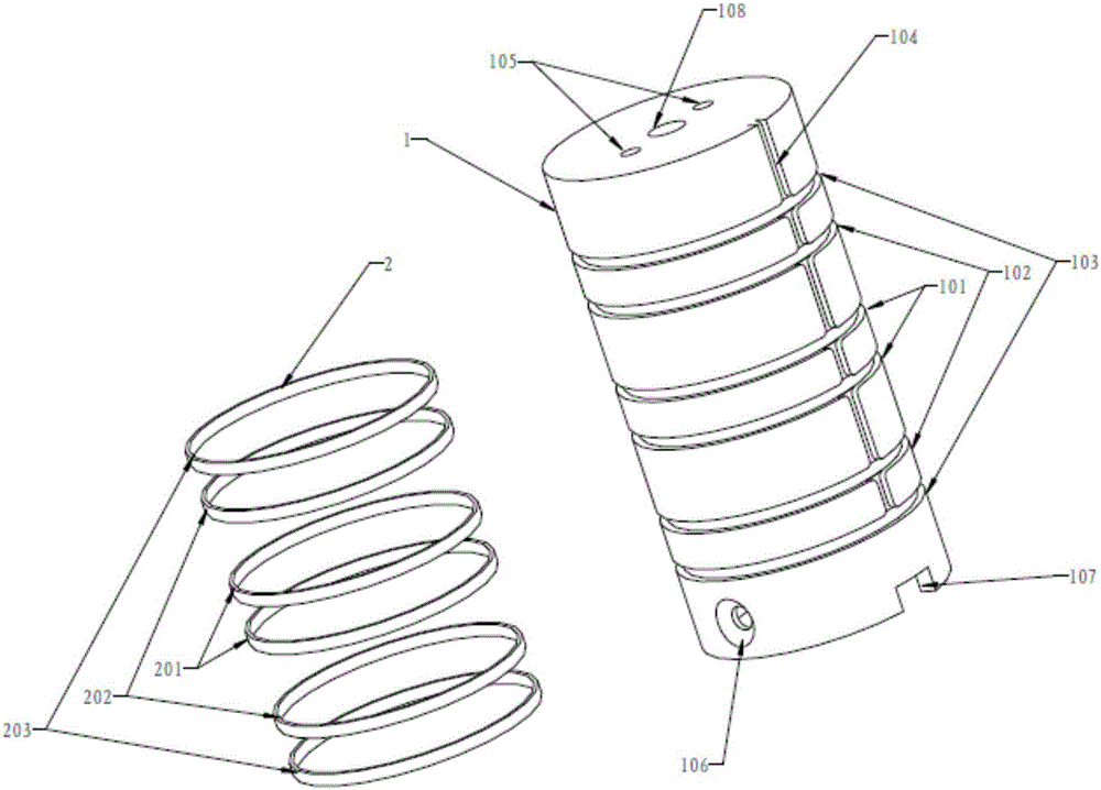
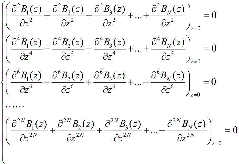
[0059] When the present invention is implemented, the coil support frame 1 is provided with 3 pairs of annular winding grooves, centered on the central cross-section of the coil support frame 1, and from the inside to the outside are the first pair of annular winding grooves 101, the second pair of annular winding grooves Winding groove 102, the third pair of annular winding grooves 103, the radial distance of the first pair of annular winding grooves 101 is 0.3 times its radius, and the radial distance of the second pair of annular winding grooves 102 is 1.5 times its radius, the radial distance of the third pair of annular winding grooves 103 is 2 times its radius, and the number of coil turns in each groove is the same, which is 12 turns. The simulation and experimental results show that the constructed longitudinal static The uniformity of magnetic field strength is better than 0.1%.

[0060] In the present invention, multiple pairs of ring coils are used as the coils for ...


PUM


Abstract

The invention provides a high precision static magnetic field generating device for a nuclear magnetic resonance gyroscope. The device includes a coil support skeleton and a static magnetic field coil. Specifically, the coil support skeleton is cylindrical, and is internally equipped with an atom gas chamber and heating related structural parts, and the side wall of the coil support skeleton is provided with a plurality of symmetrically distributed annular winding grooves for fixing the static magnetic field coil. The static magnetic field coil consists of multiple groups of longitudinally symmetric circular coils, and the symmetric plane is a central cross section of the coil support skeleton, the coils are wound by one enamelled copper wire, and each group has the same number of windings. Through specific location distribution control, the high precision static magnetic field generating device provided by the invention can provide a high precision static magnetic field with extremely high uniformity for an area where the gas chamber of the nuclear magnetic resonance gyroscope is located. Compared with the prior art, the high precision static magnetic field generating device provided by the invention has the advantages of good magnetic field uniformity, more compact structure, easy installation and maintenance, and easy realization of engineering.

Description

technical field [0001] The invention relates to the technical field of magnetic field generation for nuclear magnetic resonance gyroscopes, in particular to a high-precision static magnetic field generator for nuclear magnetic resonance gyroscopes, which is used to generate high-precision, high-stability longitudinal magnetic fields required by the gyroscopes. It can be used in fields such as strategic and tactical weaponry, miniature space vehicles and the like. Background technique [0002] The nuclear magnetic resonance gyroscope has the characteristics of small size, low power consumption, high performance, and large dynamic range, and has become the research focus and hotspot of new inertial devices. The nuclear magnetic resonance gyroscope uses the Larmor precession of the nuclear spin magnetic moment to perceive the rotation information of the carrier. In theory, it is necessary to prepare a uniform, stable and high-precision static magnetic field in the longitudinal ...

Claims


Application Information

Patent Timeline
Patent Type & Authority Applications(China)
IPC IPC(8): G01C19/62
CPCG01C19/62
Inventor 王妍刘院省阚宝玺王学锋周维洋石猛邓意成李新坤赵连洁
Owner BEIJING INST OF AEROSPACE CONTROL DEVICES
Learn More