Supersonic sand blasting gun

A sandblasting gun and supersonic technology, applied in the field of sandblasting gun structure design, can solve the problems of affecting the speed of sand particles, affecting the speed of airflow, and many components, so as to achieve the effect of improving wear resistance, reducing collision and reducing wear

Active Publication Date: 2017-03-22
NANJING UNIV OF AERONAUTICS & ASTRONAUTICS
View PDF5 Cites 11 Cited by
  • Summary
  • Abstract
  • Description
  • Claims
  • Application Information

AI Technical Summary

Problems solved by technology

This method has some deficiencies: first, the inner cavity of the structure has an annular wedge-shaped surface and an annular Laval tube formed by a truncated cone-shaped sand inlet into the inner cavity; The throat of the Laval tube is formed by the surface; the contraction and expansion surfaces of the Laval tube are formed by the shape surface and the wedge-shaped surface of the end of the truncated cone-shaped sand nozzle, and they are all conical
It can be seen that the quality of the flow field at the outlet of the Laval tube must be poor, forming scattering, which makes the sand particles almost always collide with the pipe wall, seriously affecting the sand particle velocity
Second, the high-pressure gas is provided by a single air inlet, and the output is made by the annular Laval tube, and after forming a supersonic airflow, it flows to the shrinking tube, which makes the shock wave energy formed at the axisymmetric position at the exit of the Laval tube interact with each other. Offset, affecting air velocity, which in turn affects sand particle velocity
Although this method can make solid particles achieve supersonic speed, due to the effect of combustion heat transfer, the high-temperature flame flow ejected will inevitably affect the erosion test object; because the airflow velocity generated by this method is affected by combustion, heat transfer and Influenced by many complicated factors such as pneumatic conveying, it is definitely not easy to precisely control the air flow and the velocity of solid particles; this method involves many components, complex equipment structure, and cumbersome operation

Method used


Image

  • Supersonic sand blasting gun
  • Supersonic sand blasting gun
  • Supersonic sand blasting gun

Examples


Embodiment Construction

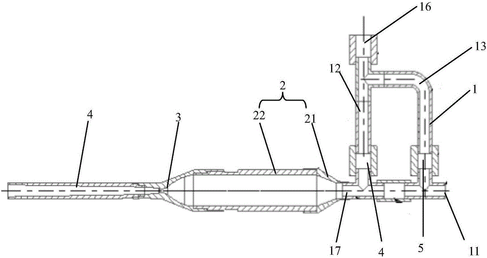
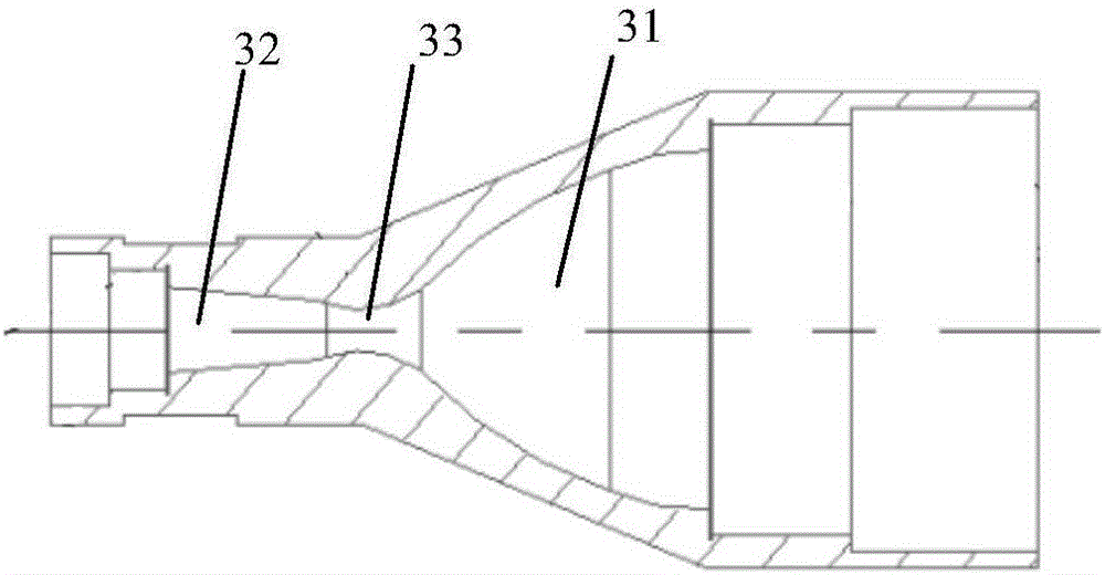
[0020] see figure 1 class figure 2 As shown, a supersonic sandblasting gun includes a sand inlet device 1, an expansion tube 2 connected to the sand outlet 17 of the sand inlet device 1, a Laval tube 3 connected to the expansion tube 2, and an acceleration tube 4 connected to the Laval tube 3 The expansion pipe 2 includes a gradually expanding transition pipe 21 connected to the sand outlet and a main body 22 (also called a sand mixing pipe) extending forward from the transition pipe 21, and the diameter of the main body 22 is larger than that of the outlet. Diameters of sand hole, Laval tube 3 and accelerating tube 4. The expansion tube 22 expands the diameter of the channel so as to adapt to the recommended contraction ratio of the Laval tube 3 (the ratio of the tube diameter before contraction to the tube diameter after contraction) so that the airflow in the tube can be decelerated and pressurized in the Laval tube 3 , to reserve appropriate potential energy; at the sam...


PUM


Abstract

The invention discloses a supersonic sand blasting gun which comprises a laval tube, an expansion tube communicated with the laval tube and an acceleration tube communicated with the laval tube. A sand mulling tube uses a design method of air flow deceleration and sand acceleration to enable sand and air to be evenly mixed before passing through the laval tube; the acceleration tube uses a design method of a shaped surface with a small expansion angle, so that the sand can continuously obtain larger boost to further accelerate to the set supersonic velocity and further reduce the effect of on-way resistance to the air flow; the laval tube uses a curve design method, so that the abrasion of the sand to a throat is reduced, the high-quality air flow with zero axial velocity gradient can be obtained at an outlet of the laval tube, the sand can move along the axis as possible to reduce the collision between the sand and the tube wall, and the abrasion resistance of the spray gun can be improved fundamentally.

Description

technical field [0001] The invention relates to the field of sandblasting gun structure design. Background technique [0002] In the past ten years, the research on the anti-sand erosion performance of materials has made continuous progress. At present, the research on sand erosion mainly uses gas or liquid as sand particles to accelerate erosion and impact the target. The former is gas-solid erosion and the latter is liquid-solid erosion. The erosion resistance test of metal materials usually uses dry air to accelerate the erosion of sand particles, because air can reduce the influence of factors other than sand particles on metal research objects more than liquid. However, relying on the air to push the sand to accelerate it, the efficiency is very limited. To obtain greater sand particle velocity, it can only be achieved by increasing the air velocity. [0003] One way to increase the air flow rate is to use the annular Laval tube to form a supersonic airflow with a f...

Claims


Application Information

Patent Timeline
Patent Type & Authority Applications(China)
IPC IPC(8): G01N3/56G01N3/02
CPCG01N3/02G01N3/565
Inventor 颜诚陈伟李炎赵振华
Owner NANJING UNIV OF AERONAUTICS & ASTRONAUTICS
Why Eureka
Try Eureka