
Optical system pre-positioning method

An optical system and pre-positioning technology, applied in scientific instruments, measurement and instrumentation by measuring the change of optical properties of materials when they are stressed, can solve the problem of taking a long time and limiting the use of Raman spectroscopy systems. , spend a few minutes or even ten or dozens of minutes and other problems to achieve the effect of shortening the positioning time

Inactive Publication Date: 2020-01-10
INST OF HIGH ENERGY PHYSICS CHINESE ACAD OF SCI
View PDF4 Cites 0 Cited by
  • Summary
  • Abstract
  • Description
  • Claims
  • Application Information

AI Technical Summary

Problems solved by technology

The pre-positioning process usually takes a long time. On the one hand, after placing the Cell bracket with the DAC fixed on the translation stage on the turntable in the first experiment, there are differences between the sample cavity in the DAC and the center of the turntable in the three directions of XYZ, and the maximum The difference can be several millimeters. At this time, it is necessary to first move the horizontal and vertical directions of the translation stage on the turntable so that the X-rays can pass through the diamond anvil sample chamber. This process is usually "blind shift" and usually takes a few minutes. Even tens or tens of minutes, other reasons for the pre-positioning process taking a long time are the small differences in the size of different DACs, the slightly different positions where the DAC is installed on the Cell holder, and the size of the diamond-anvil sample cavity and the different seals, etc. factors can cause the pre-targeting process to take longer
Usually, the experimental station user’s experimental machine time is strictly controlled for 12 or 24 hours. If the user frequently replaces the DAC, the position of the diamond-to-anvil sample cavity must be repositioned every time the DAC is replaced. If the pre-positioning process is not very smooth each time, this will cause The user spends more time accumulatively on the positioning of the diamond on the anvil sample cavity, reducing the user's effective experiment time; and during the special opening period of the X-ray diffraction system, the Raman spectroscopy system can only be used as a ruby ​​fluorescence pressure measurement function, Limits the Raman detection function of the Raman spectroscopy system

Method used


Image

  • Optical system pre-positioning method
  • Optical system pre-positioning method
  • Optical system pre-positioning method

Examples


Embodiment Construction

[0046] Example embodiments will now be described more fully with reference to the accompanying drawings. Example embodiments may, however, be embodied in many forms and should not be construed as limited to the examples set forth herein; rather, these embodiments are provided so that this disclosure will be thorough and complete and will fully convey the concept of example embodiments to those skilled in the art. The described features, structures, or characteristics may be combined in any suitable manner in one or more embodiments. In the following description, numerous specific details are provided in order to give a thorough understanding of embodiments of the present disclosure. However, those skilled in the art will appreciate that the technical solutions of the present disclosure may be practiced without one or more of the specific details being omitted, or other methods, components, devices, steps, etc. may be adopted. In other instances, well-known technical solution...


PUM


Abstract

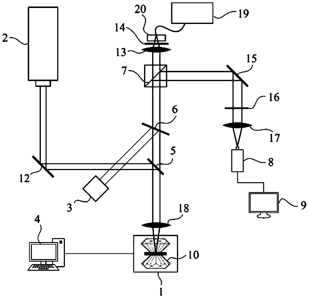
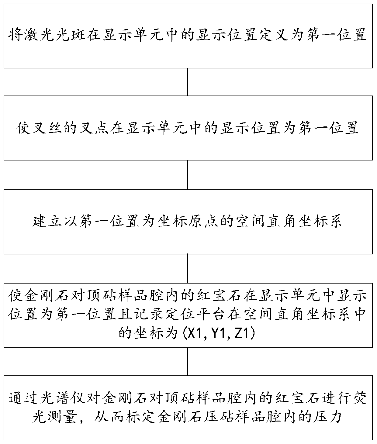
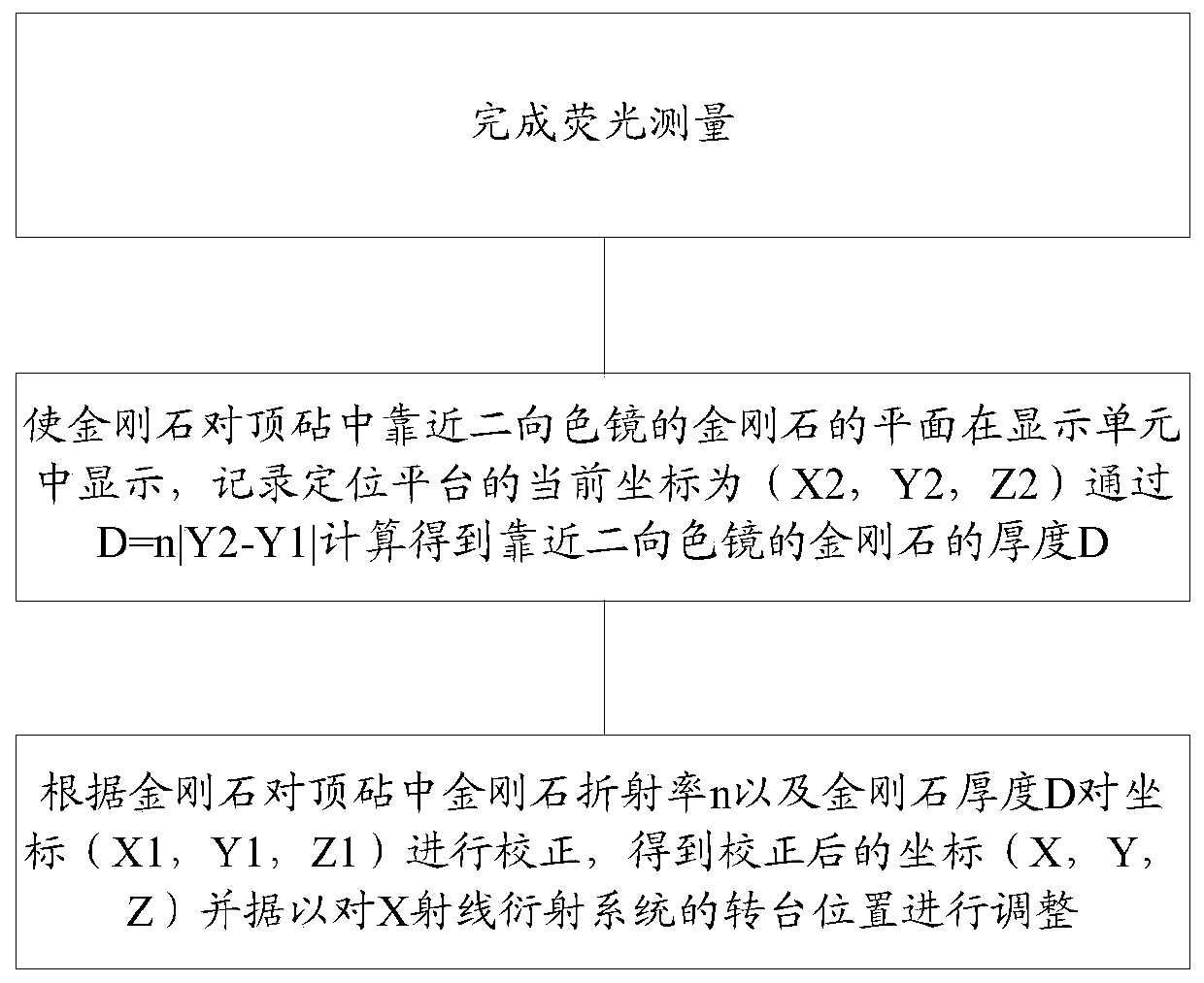
The invention provides an optical system and a fluorescence measurement and pre-positioning method thereof. The optical system comprises a positioning platform, a laser source, an illuminating light source, a control unit, a dichroscope, a semi-reflection mirror, a beam splitter, an image pickup unit and a display unit. The method comprises the following steps: positioning a first position by laser, wherein the display position of the cross point of cross hairs in the display unit is the first position; placing a diamond anvil cell on a positioning platform; moving the positioning platform so that the display position of ruby in a diamond anvil cell sample cavity in the display unit is the first position to finish fluorescence measurement; recording the coordinates of the positioning platform; and finally, correcting the recorded coordinates according to the diamond refractive index in the diamond anvil cell. In the invention, pressure measurement and pre-positioning of the diamond anvil cell sample cavity can be realized, the calibration of pressure of the sample cavity depending on a Raman spectral system is avoided, and the positioning time of a diamond anvil cell sample cavity experiment by an X-ray diffraction system is shortened.

Description

technical field [0001] The invention relates to the technical field of high-voltage experiments, and in particular, to an optical system, a fluorescence measurement method of the optical system, and a pre-positioning method of the optical system. Background technique [0002] As an important thermodynamic quantity, pressure plays an important role in the research of condensed matter physics. Under the action of pressure, the volume of the substance shrinks, the free energy changes accordingly, and the structure of the substance changes accordingly, such as the substance solidifies and crystallizes from a liquid; the solid that was originally a crystal may change its crystal structure or electronic structure; Under high pressure, semiconductors and insulators may undergo metal transformation, etc. These phenomena are usually called high-voltage phase transitions. The exploration of its change mechanism and process is an extremely rich field in the field of high-voltage scienc...

Claims


Application Information

Patent Timeline
Patent Type & Authority Patents(China)
IPC IPC(8): G01N23/20008G01L1/24
CPCG01L1/24G01N23/20008G01N2223/056G01N2223/1016G01N2223/32G01N2223/605
Inventor 李晓东宫宇李延春杨栋亮
Owner INST OF HIGH ENERGY PHYSICS CHINESE ACAD OF SCI
Learn More