Fuel-rod end plug pressing machine and application method

A rod-end plugging machine and fuel rod technology, which is applied in the manufacture of reactors, reactors, and reduction of greenhouse gases, etc., can solve problems such as poor sealing, increased costs, and low efficiency, and achieve stable connection, easy adjustment, and convenient operation Effect

Active Publication Date: 2017-03-22
CNNC JIANZHONG NUCLEAR FUEL +1
View PDF5 Cites 7 Cited by
  • Summary
  • Abstract
  • Description
  • Claims
  • Application Information

AI Technical Summary

Problems solved by technology

[0004] The purpose of the present invention is to overcome the above-mentioned deficiencies in the existing fuel rod assembly technology, which are easy to cause poor sealing, increase the detection steps of sealing, increase cost, and inefficiency, and provide a plugging machine for fuel rod end plugs and its use. The method improves the sealing performance of the fuel rod, improves the assembly efficiency, and simplifies the assembly steps

Method used


Image

  • Fuel-rod end plug pressing machine and application method
  • Fuel-rod end plug pressing machine and application method
  • Fuel-rod end plug pressing machine and application method

Examples


Embodiment 1

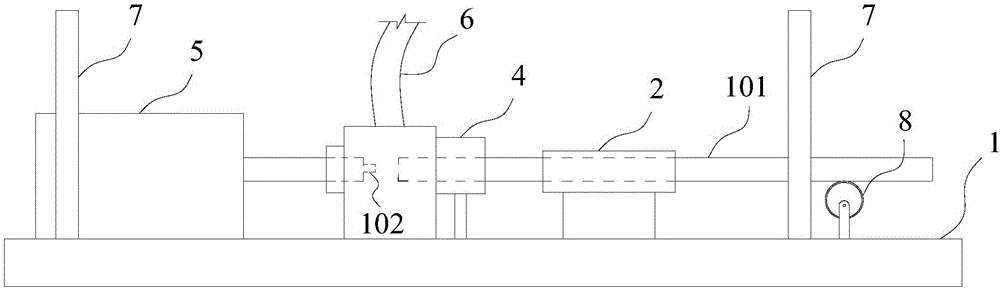
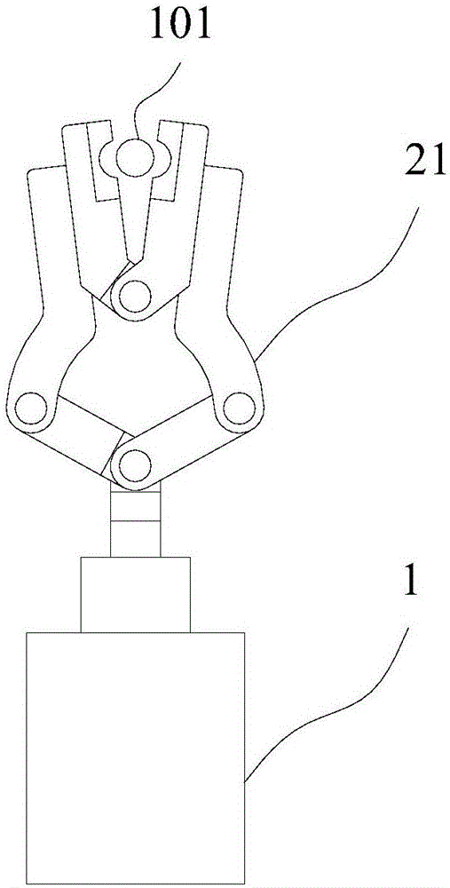
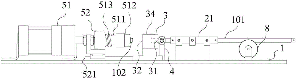
[0060] Such as figure 1 As shown, a fuel rod end plug corking machine includes a base 1, a drive system and a control system, and a fixing mechanism 2, an operating room 3, a sealing mechanism 4 and a pushing mechanism 5 are all arranged on the base 1, giving The exhaust mechanism 6 is connected to the operating room 3, the control system controls the driving system to drive the pushing mechanism and the supply and exhaust mechanism, the fixing mechanism 2 is used to fix the fuel rod 101, and the base 1 There is also a support wheel 8 for supporting the other end of the plugging end of the fuel rod 101 to prevent the cladding tube from being damaged due to the rod body being too long and falling under gravity. The sealing mechanism 4 is located in the operating room 3 On one side, the plugging end of the fuel rod 101 extends into the operation chamber 3 through the sealing mechanism 4, and the pushing mechanism 5 is located on the opposite side of the sealing mechanism 4, and ...

Embodiment 2

[0063] A method for using a fuel rod end plug corking machine, comprising using a fuel rod end plug corking machine as in Embodiment 1, the method of use comprising the following steps:

[0064] Step 1. Put the plugging end of the fuel rod 101 through the sealing mechanism 4 and put it into the operation chamber 3;

[0065] Step 2, using the sealing mechanism 4 to seal the plugging end of the fuel rod 101;

[0066] Step 3, fixing the fuel rod 101 with the fixing mechanism 2;

[0067] Step 4, put the end plug 102 into the push mechanism 5 and fix it;

[0068] Step 5, the pushing mechanism 5 and the sealing mechanism 4 are adapted to the operating chamber 3, and the operating chamber 3 is formed into a closed cavity;

[0069] Step 6, the air supply and exhaust mechanism 6 vacuumizes the cavity;

[0070] Step 7, the air supply and exhaust mechanism 6 fills the cavity with inert gas;

[0071] Step 8: The pushing mechanism 5 presses the end plug 102 into the plugging end of the...


PUM


Abstract

The invention discloses a fuel-bar end plug pressing machine and an application method. The device comprises a base, a driving system and a control system. A fixing mechanism, an operating chamber, a sealing mechanism and a pushing mechanism are arranged on the base, an air feeding and discharging mechanism is connected to the operating chamber, and the control system controls the driving system to drive the pushing mechanism and the air feeding and discharging mechanism. The application method of the device includes the steps that vacuumizing and inflating are carried out in the sealed operating chamber, and after the proportion of inflated inert gas reaches a preset proportion, plug pressing is directly carried out till a plug is tightly pressed. By means of the device, the sealing effect of a fuel bar can be improved, sealing leakage detection is facilitated, operating is more convenient, the mixing possibility of other air ingredients is reduced, contact of a core block in the fuel bar and a shell covering pipe is effectively delayed, and the performance and the safety of the fuel bar are improved. By means of the application method, the volume ratio of the inflated gas can be accurately controlled, the plug pressing step is simplified, the performance and the safety of the fuel bar are improved, the cost is reduced, and the production efficiency is improved.

Description

technical field [0001] The invention relates to the field of fuel in the nuclear industry, in particular to a plugging machine for fuel rod end plugs and a use method thereof. Background technique [0002] Against the backdrop of increasingly serious environmental pollution and energy crises, the development of nuclear power as a new type of clean energy is bound to be greatly accelerated. Nuclear fuel is usually in the form of uranium dioxide ceramic pellets sintered from uranium mixture powder. The porcelain core is a cylinder with a diameter of 1 cm and a height of 1 cm. Hundreds of pellets are stacked together into a slender zirconium alloy cladding tube with a diameter of 1 cm, a length of about 4 meters, and a wall thickness of about 1 mm. Because the nuclear fission reaction is like burning atoms, it is called fuel. Great. [0003] The fuel rod manufacturing process mainly includes fuel pellet preparation, cladding tube preparation and fuel rod assembly. During fue...

Claims


Application Information

Patent Timeline
Patent Type & Authority Applications(China)
IPC IPC(8): G21C21/02
CPCG21C21/02Y02E30/30
Inventor 尤勇唐臻宇杨通高骆宾
Owner CNNC JIANZHONG NUCLEAR FUEL
Why Eureka
Try Eureka