Same-phase traction power supply system suitable for high-speed electrified railway

A traction power supply system and electrified railway technology, applied in the field of in-phase traction power supply technology system, can solve the problems of high construction cost, high overall investment and high cost

Active Publication Date: 2017-03-22
TSINGHUA UNIV
View PDF10 Cites 26 Cited by
  • Summary
  • Abstract
  • Description
  • Claims
  • Application Information

AI Technical Summary

Problems solved by technology

[0007] The disadvantage of using the unbalanced traction transformer represented by patents 6-9 to realize the same-phase traction power supply system is that the voltage phasors of the ports on both sides of the active compensation device that cooperates with it do not constitute a vertical relationship. The active compensation device required for sequence component compensation has a relatively large capacity (take the high-speed electrified railway using the same phase power supply system as an example, assuming that the traction load rated capacity of the traction substation using the unbalanced traction transformer is 1 per unit, then completely The per-unit value of t

Method used


Image

  • Same-phase traction power supply system suitable for high-speed electrified railway
  • Same-phase traction power supply system suitable for high-speed electrified railway
  • Same-phase traction power supply system suitable for high-speed electrified railway

Examples


Embodiment Construction

[0042] The following is a detailed description of a co-phase traction power supply system suitable for high-speed electrified railways proposed by the present invention in combination with the drawings and embodiments as follows:

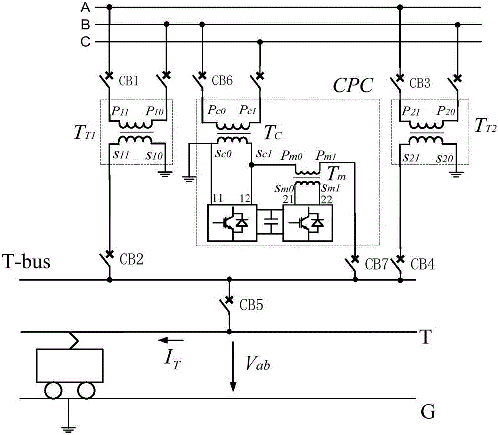
[0043] The present invention proposes a co-phase power supply system suitable for high-speed electrified railways. When the system is a direct power supply system and adopts an active compensation configuration, its structure diagram is as follows figure 1 Shown, including main traction transformer T T1 , Spare traction transformer T T2 And the in-phase compensator CPC; the in-phase compensator CPC is an active compensation configuration mode, which is composed of a compensation transformer T C , "Back-to-back" converter and matching transformer T m Composition; main traction transformer T T1 , Spare traction transformer T T2 , Compensation transformer T in the in-phase compensator CPC C , Matching transformer T m All are single-phase transformer structur...


PUM


Abstract

The invention provides a same-phase traction power supply system suitable for a high-speed electrified railway, and belongs to the technical field of traction power supply and electric power transmission and distribution. The same-phase traction power supply system includes traction transformers and a same-phase compensator which are mutually independent, and the traction transformers and a compensation transformer and a matching transformer in the same-phase compensator are of single-phase structures. The primary windings of the traction transformers and the primary winding of the compensator transformer form V, and a connection method of V is as follows: one end of the primary winding of the matching transformer is connected with one end of the secondary winding of the compensation transformer, and other end of the primary winding is connected to the positive electrode of a traction busbar; the other end of the secondary winding of the compensation transformer is connected to the ground or the negative electrode of the traction busbar, alternating current ports of one side of ''back-to-back'' converters are connected to the secondary winding of the compensation transformer, and the other side is connected to the secondary winding of the matching transformer; and the same-phase compensator adopting hybrid compensation configuration also includes a fixed capacitor branch circuit and a fixed reactor branch circuit. The same-phase traction power supply system suitable for the high-speed electrified railway can achieve an effect that the capacity of both active and passive compensation devices is the lowest configuration, and a relatively high capacity utilization rate of the transformers is maintained at the same time.

Description

Technical field [0001] The invention belongs to the technical field of traction power supply systems and electric power transmission and distribution, and particularly relates to a co-phase traction power supply technical system suitable for high-speed electrified railways. Background technique [0002] Railway traction power supply systems in most countries in the world, including China, all adopt the power frequency single-phase unilateral power supply system. In order to alleviate the unbalanced impact of single-phase traction load on the external power system, adjacent traction substations adopt The phase sequence rotation mode is connected to the external power system. Since the voltage phases of the power supply arms on both sides of the "electric split phase" formed by each traction substation are different, this system is also called the out-of-phase traction power supply mode. Out-of-phase traction power supply makes electric locomotives inevitably have a "power-off-re-...

Claims


Application Information

Patent Timeline
IPC IPC(8): H02J3/18
CPCY02E40/30H02J3/1821H02J3/1878
Inventor 魏应冬姜齐荣韩英铎刘文华袁志昌张树卿谢小荣宋强张春朋于庆广
Owner TSINGHUA UNIV
Why Eureka
Try Eureka