A hollow cup motor rotor baking device

A technology for motor rotors and baking devices, which is applied in the direction of electromechanical devices, manufacturing motor generators, electrical components, etc., can solve the problems of occupying the operating time of operators, increasing the temperature of operators, and scalding, so as to reduce production costs and maintain operations. The effect of improving safety and productivity

Active Publication Date: 2019-08-13
ONCE TOP MOTOR MFG
View PDF6 Cites 0 Cited by
  • Summary
  • Abstract
  • Description
  • Claims
  • Application Information

AI Technical Summary

Problems solved by technology

Manual operation to complete the above operations will take up the operating time of the operator, which restricts the production cost of the coreless motor
In addition, due to the relatively high baking temperature, manual operation will also increase the risk of high temperature burns to operators

Method used


Image

  • A hollow cup motor rotor baking device
  • A hollow cup motor rotor baking device
  • A hollow cup motor rotor baking device

Examples


Embodiment 1

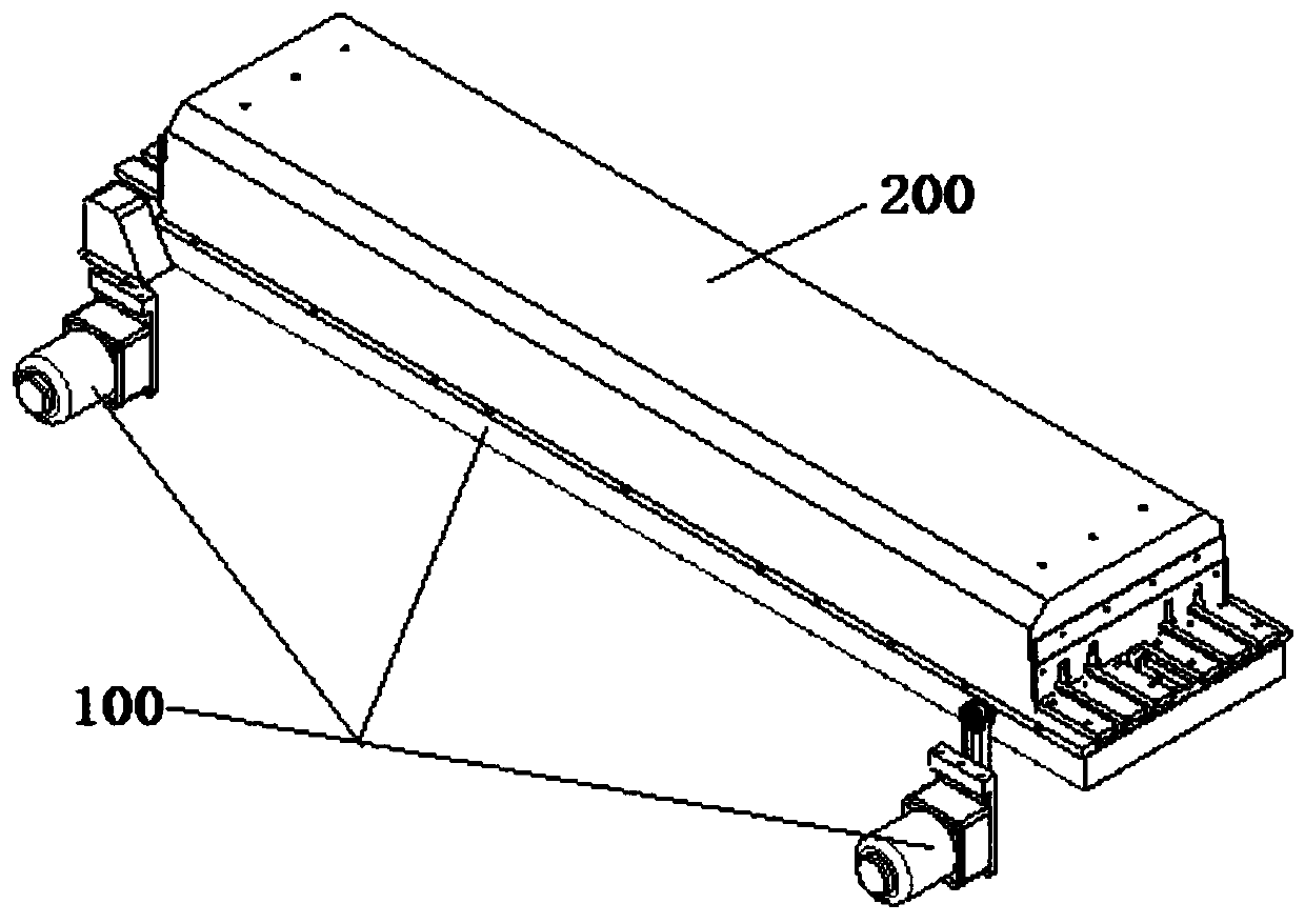
[0035] Such as Figure 2-5 As shown, the present invention provides a hollow-cup motor rotor baking device, including: a hollow-cup motor rotor conveyor 100 and a heat shield 200 buckled on the hollow-cup motor rotor conveyor; the hollow-cup motor rotor conveys The machine 100 includes a baking conveying section 110 and a feeding conveying section 120. The conveying speed of the baking conveying section 110 is lower than the conveying speed of the feeding conveying section 120; the heat shield 200 is provided with baking heating Device 210; the size of the heat shield 200 is adapted to the shape of the baking conveying section 110; the heat shield 200 is perpendicular to the conveying direction of the hollow-cup motor rotor conveyor at both ends are respectively provided with inlet Material port 201 and discharge port 202.

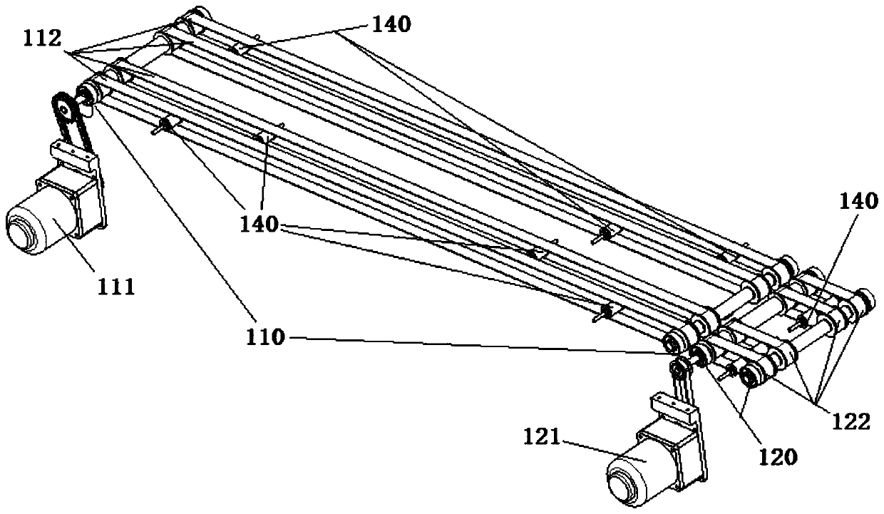
[0036] image 3 As shown, the baking conveying section 110 of the conveyor 100 is provided with a first driving motor 111 and a plurality of baking conveyin...

Embodiment 2

[0042] Image 6 As shown, in this embodiment, on the basis of Embodiment 1, a temperature detection device 132 is provided in the baking conveying section. By setting the temperature detection device in the baking conveying section, the present invention helps to achieve the technical effect of adjusting different baking temperatures for different components of the glue. The temperature detection device arranged in the baking conveying section can instantly feedback the insulation The instant temperature of the baking temperature field in the heat hood provides strong structural support for accurately baking the hollow cup motor rotor at all times; further, the temperature detection device installed in the baking conveying section can also obtain additional monitoring baking heating devices The technical effect of whether it is working normally helps to detect equipment failures in time, and then achieve the technical effect of timely stop loss.

[0043] Preferably, such as Imag...

Embodiment 3

[0046] Figure 7 As shown, the structural diagram of the heat shield placed upside down in this embodiment, this embodiment is based on the above-mentioned embodiment, the upper end surface of the heat shield 200 is provided with a number of air supply devices 220 in a uniformly distributed form The air supply device 220 includes: a ventilation plate 221, a wind cover 222 and a fan 223; the ventilation plate 221 is inlaid on the upper end surface of the heat shield, the ventilation plate is evenly distributed with ventilation holes; the wind One end of the cover 222 is firmly connected to the ventilation plate 221, and the other end of the wind cover 222 is fixedly provided with the fan 223.

[0047] The present invention further disposes several air supply devices in a uniformly distributed form on the upper end surface of the heat shield, which helps to achieve the technical effect of uniformly pushing the heat generated by the baking heating device to the hollow cup motor rotor...


PUM


Abstract

The invention discloses a hollow cup motor rotor baking device with a simple structure and automatic baking. After the baking is completed, a hollow cup motor rotor is automatically transported to a next operation position rapidly. The structure of the hollow cup motor rotor baking device comprises a hollow cup motor rotor conveyor and a heat shield buckled to the hollow cup motor rotor conveyor, the hollow cup motor rotor conveyor comprises a baking conveying section and a feeding conveying section, and the conveying speed of the baking conveying section is lower than that of the feeding conveying section. The heat shield is internally provided with a baking heating device, and the size of the heat shield is adapted to the shape of the baking conveying section. Two ends of the heat shield which are perpendicular to the conveying direction of the hollow cup motor rotor conveyor are provided with a material inlet and a material outlet. According to the device, the baking of the hollow cup motor rotor which is subjected to dispensing can be automatically completed.

Description

Technical field [0001] The invention relates to the technical field of automatic manufacturing equipment for hollow-cup motors, in particular to a hollow-cup motor rotor baking device. Background technique [0002] The coreless motor is a DC permanent magnet and servo micromotor. The main difference from ordinary motors is that it uses a coreless rotor, also called a coreless rotor. The stator is a magnetic steel inside. figure 1 The hollow cup motor shown in the prior art has a structure including: a back cover 1, a brush holder 2, a hollow cup rotor 3, a gasket 4, a neodymium iron boron magnet 5, a stator 6, a bearing 7, and a circlip 8. . Coreless motors have outstanding energy-saving, control and drag characteristics. They mainly include: 1. Energy-saving characteristics: energy conversion efficiency is very high, and its maximum efficiency is generally above 70%, and some products can reach above 90% (common iron core motors) At 20-50%). 2. Control characteristics: starti...

Claims


Application Information

Patent Timeline
Patent Type & Authority Patents(China)
IPC IPC(8): H02K15/12
CPCH02K15/12
Inventor 张用万
Owner ONCE TOP MOTOR MFG
Why Eureka
Try Eureka