Permanent magnet assisted bearingless synchronous reluctance motor

A synchronous reluctance motor, bearingless technology, used in synchronous machines, synchronous motors with stationary armatures and rotating magnets, synchronous machine parts, etc., can solve the problem of low salient pole ratio, low torque density, motor power Low factor, etc., to achieve the effect of increasing torque density, reducing system cost, and wide range of constant power speed regulation

Pending Publication Date: 2017-03-22
JIANGSU UNIV
View PDF9 Cites 11 Cited by
  • Summary
  • Abstract
  • Description
  • Claims
  • Application Information

AI Technical Summary

Problems solved by technology

[0005] The purpose of the present invention is to propose a high salient pole ratio, high power factor and torque density in order to solve the problems of low motor power factor and

Method used


Image

  • Permanent magnet assisted bearingless synchronous reluctance motor
  • Permanent magnet assisted bearingless synchronous reluctance motor
  • Permanent magnet assisted bearingless synchronous reluctance motor

Examples


Embodiment Construction

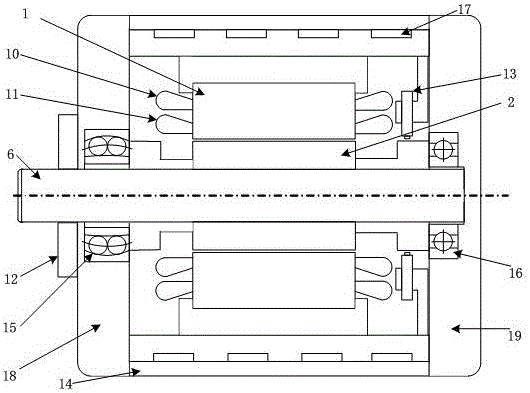
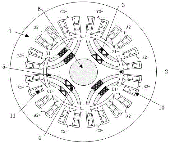
[0026] see figure 1 and figure 2 , the permanent magnet assisted bearingless synchronous reluctance motor of the present invention includes a stator 1, a rotor 2 and a rotating shaft 6, the rotor 2 is coaxially located inside the stator 1, the rotor 2 is coaxially sleeved outside the rotating shaft 6, and the rotor 2 is slotted for placement Spindle 6. The stator 1 is wound with inner and outer double-layer windings, the outer winding is a torque winding 10 , and the inner winding is a suspension force winding 11 . Outside the stator 1 is a casing 14, the left and right ends of the casing 14 are respectively a left end cover 18 and a right end cover 19, the casing 14 is used to fix the stator 1, the left end cover 18 and the right end cover 19, and the left end cover 18 passes through The self-aligning ball bearing 15 is connected to the rotating shaft 6 , and the right end cover 19 is connected to the rotating shaft 6 through the auxiliary bearing 16 . The self-aligning b...


PUM


Abstract

The invention discloses a permanent magnet assisted bearingless synchronous reluctance motor in the field of motor manufacturing. Four groups of magnetic barrier bodies are uniformly arranged inside a rotor along the peripheral direction; each group of magnetic barrier bodies consists of circular arc-shaped inner magnetic barriers and circular arc-shaped outer magnetic barriers which are arranged at intervals along the radial direction, a permanent magnet mounting groove is formed in the middle section of each inner magnetic barrier and the middle section of each outer magnetic barrier respectively, and a permanent magnet is embedded in each permanent magnet mounting groove; the inner magnetic barriers, the outer magnetic barriers and the permanent magnets are symmetrically distributed along the d axis of the motor; a torque winding is wound on the outer layer of a stator, and a suspension force winding is wound on the inner layer of the stator; the magnetizing directions of the permanent magnets in two adjacent groups of magnetic barrier bodies are opposite, the magnetizing directions of the permanent magnets in the same group of magnetic barrier bodies are the same, the end, close to an air gap, of each permanent magnet is N pole, and the end, close to a rotating shaft, of each permanent magnet is S pole; the magnetic barriers are added onto a direct-axis magnetic circuit of the rotor, and meanwhile layered rectangular permanent magnet structures are adopted on the direct-axis magnetic circuit of the rotor, so that the direct-axis inductance of the motor is greater than the quadrature-axis inductance, and the torque density of the motor is increased.

Description

technical field [0001] The invention relates to a multivariable, nonlinear, strong coupling bearingless synchronous reluctance motor, which belongs to the field of motor manufacturing and control, and is used in high-speed electric drive occasions, machine tool electric spindles, bioengineering, toxic substance transmission, semiconductor manufacturing and other industries field and aerospace and other military fields. Background technique [0002] The stator torque winding of the bearingless synchronous reluctance motor is stacked with a levitation force winding with a pole pair number difference of 1. Controlling these two sets of windings can simultaneously generate electromagnetic torque and radial levitation force. Therefore, the bearingless synchronous reluctance motor combines the advantages of magnetic bearings and synchronous reluctance motors, and can maximize the use of reluctance torque. The salient pole rotor bearingless synchronous reluctance motor has the adv...

Claims


Application Information

Patent Timeline
IPC IPC(8): H02K21/02H02K21/14H02K1/27H02K1/16
CPCH02K1/16H02K1/276H02K21/028H02K21/14H02K2213/03
Inventor 朱熀秋丁海飞刁小燕
Owner JIANGSU UNIV
Why Eureka
Try Eureka