
Optical heart rate sensor

A heart rate sensor, optical technology, applied in the optical heart rate sensor, the field of optical heart rate sensing, can solve problems such as measurement interference

Active Publication Date: 2017-03-22
SHENZHEN GOODIX TECH CO LTD
View PDF3 Cites 12 Cited by
  • Summary
  • Abstract
  • Description
  • Claims
  • Application Information

AI Technical Summary

Problems solved by technology

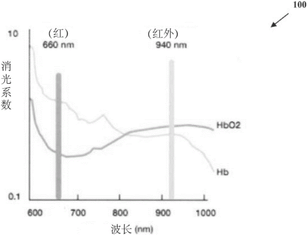
Sensitivity of optical sensors to ambient light and user motion can cause significant disturbance to measurements

Method used


Image

  • Optical heart rate sensor
  • Optical heart rate sensor
  • Optical heart rate sensor

Examples


Embodiment Construction

[0029] The heart rate sensor described herein includes the hardware and software needed to acquire heart rate data from a user wearing the heart rate sensor as part of a portable device such as a smart watch. The described heart rate sensor can continuously collect heart rate sensor data from a user and combine the heart rate sensor data with sensor data from other sensors to enhance the accuracy of sensor data analysis and provide relevant feedback information to the user. Additionally, the heart rate sensor can be paired with an external personal portable device, such as a smartphone or tablet, to correlate the collected sensor data with the activities performed by the user on the paired device. The heart rate sensor can be paired with an external personal portable device directly or through a host device that includes the heart rate sensor, such as a smart watch. Through a host device or paired external personal portable device, sensor data from a heart rate sensor can be s...


PUM


Abstract

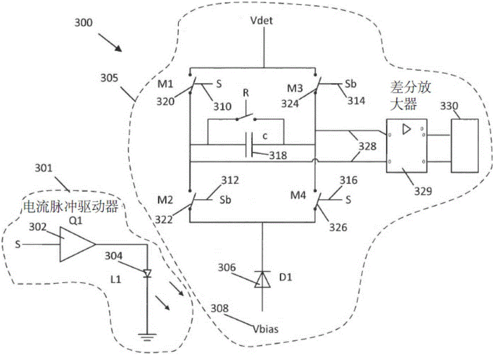
Techniques, systems and apparatus are described for implementing a heart rate sensor based on optical measurements of color response of human blood. An optical heart rate sensor can include light source circuitry including a first light emitting diode (LED) to output a first source light signal to a target measurement site, a second LED to output a second source light signal to the target measurement site, a first current pulse driver communicatively coupled to the first LED to modulate the first source light signal output from the first LED at a first predetermined frequency and a second current pulse driver communicatively coupled to the second LED to modulate the second source light signal output from the second LED at a second predetermined frequency different from the first predetermined frequency. The optical heart rate sensor can include detector circuitry including a light detecting photodiode connected to a bias voltage.

Description

[0001] Cross References to Related Applications [0002] This patent document claims the benefit of priority from US Provisional Patent Application Serial No. 62 / 028,206, filed July 23, 2014. The entire contents of the aforementioned patent applications are incorporated by reference as part of the disclosure content of this document. Background technique [0003] The present application relates to devices, techniques and systems for detecting heart rate using optical sensors. [0004] In a typical optical heart-rate sensor, a photodiode, a low-noise amplifier, and an analog-to-digital converter (ADC) are used to measure the photodiode response using LEDs with different wavelengths as light sources. Sensitivity of optical sensors to ambient light and user's motion can cause significant disturbances to the measurements. LNAs typically require more power, and the usable heart rate signal is typically only 1 / 100 to 1 / 10,000 of the total photodiode signal. Contents of the inven...

Claims


Application Information

Patent Timeline
IPC IPC(8): A61B5/024
CPCA61B5/0059A61B5/02416A61B5/02444A61B5/0261A61B5/0295A61B5/14551A61B5/14552A61B5/6898A61B5/7207A61B5/7214A61B5/7225A61B5/7228A61B5/7242A61B2560/0233A61B2560/0247A61B2562/0238A61B2562/04
Inventor 皮波何毅
Owner SHENZHEN GOODIX TECH CO LTD
Learn More