Horizontal foam pump

A foam pump, horizontal technology, applied in the field of horizontal foam pumps, can solve the problems of reduced efficiency, difficulty in discharging, reduced delivery capacity, etc.

Inactive Publication Date: 2017-03-29
GUANGZHOU TOTALL FLUID EQUIP TECH CO LTD
View PDF0 Cites 4 Cited by
  • Summary
  • Abstract
  • Description
  • Claims
  • Application Information

AI Technical Summary

Problems solved by technology

If the air content of the medium is high, it will form a large air mass in the blade, which is difficult to discharge
In severe cases, the pump may be intermittently interrupted, which will further reduce the pump's delivery capacity. Therefore, the impact of circulation on the foam pump is not only a decrease in efficiency, but also a much greater impact on flow than other centrifugal pumps.

Method used


Image

  • Horizontal foam pump
  • Horizontal foam pump
  • Horizontal foam pump

Examples


Embodiment 1

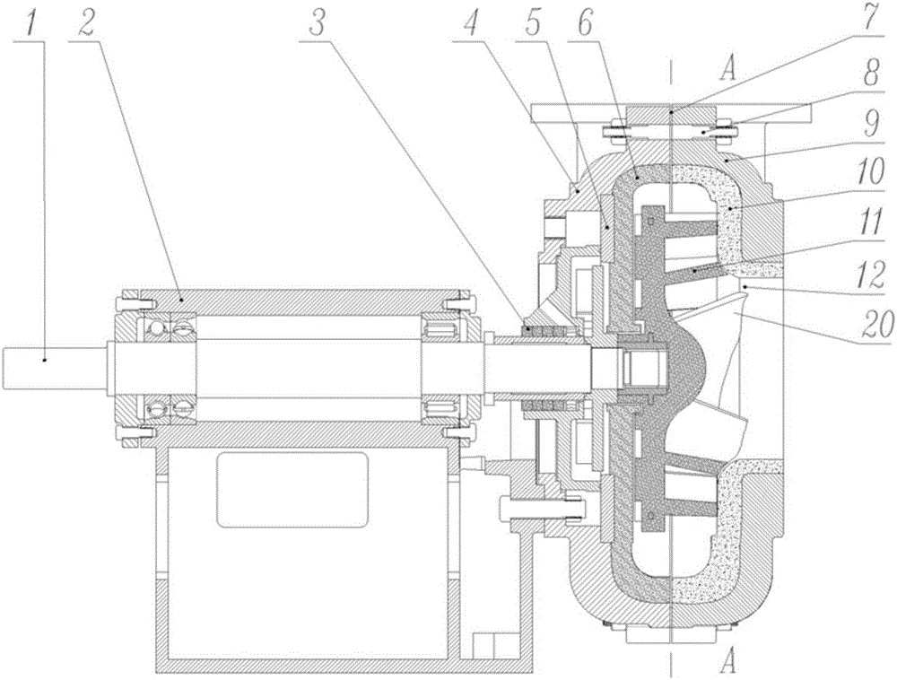
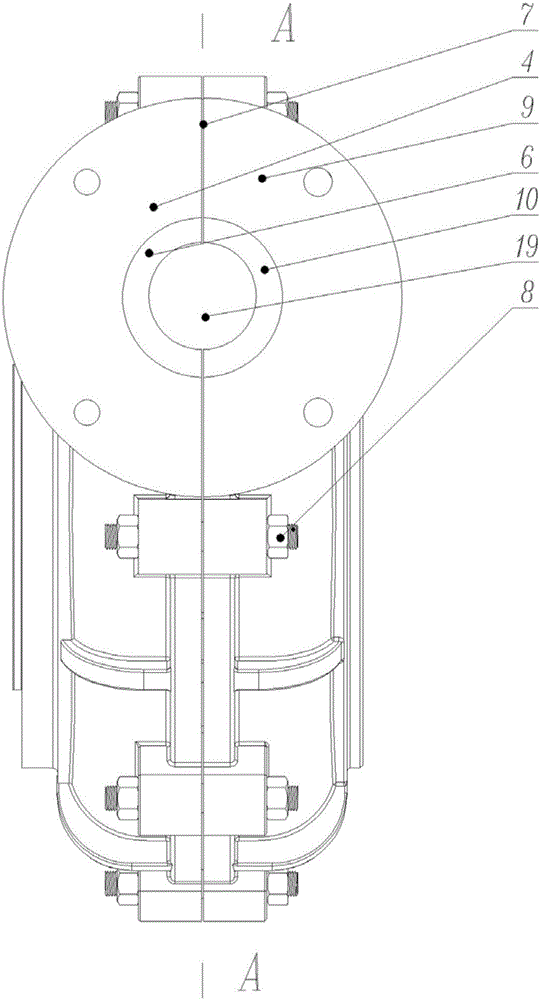
[0043] Such as Figure 1-7 as well as Figure 9As shown, a horizontal foam pump includes a pump body, the pump body is provided with a suction port 12 and a discharge port 19, the pump body is provided with an impeller 11, and the impeller 11 is provided with 3- Five main blades 13 and the same number of splitter blades 14; the splitter blades 14 are distributed between two adjacent main blades 13.

[0044] In practical applications, the setting of the splitter vanes 14 can significantly reduce the circulation intensity between the vanes, such as Figure 8 The middle is an ordinary foam pump impeller, its rotation direction is counterclockwise as shown by the arrow, and the generated circulation 16 is clockwise. And as Figure 6 The impeller of the shown embodiment 1 also rotates counterclockwise. Due to the arrangement of the splitter blades 14, the intensity of the circulation 17 is relatively high. Figure 8 The circular flow 16 in the conventional foam pump impeller sh...

Embodiment 2

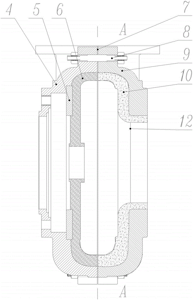
[0058] Figure 10 , Figure 11 , Figure 12 In the shown embodiment 2, the impeller 11 is made of high chromium alloy, and its main blade 13 is twisted at the inlet end 18, and the inlet end 18 extends to the suction port 12. The length of the splitter blade is 0.56 times the length of the main blade, and the front inner The lining 10 and the rear inner lining 6 are made of rubber. A front sealing lip 21 is arranged on the outer edge of the front inner lining 10, and a rear sealing lip 22 is also arranged on the corresponding position of the rear inner lining 6. The rest of the structure Similar to Example 1. The manufacturing cost of this embodiment is relatively low, and is suitable for light abrasive working conditions.


PUM


Abstract

The invention discloses a horizontal foam pump. The horizontal foam pump comprises a pump body; the pump body is provided with a suction inlet and a discharge outlet; an impeller is arranged in the pump body, is an open impeller and is provided with 3-5 main blades and 3-5 splitter blades; and each splitter blade is distributed between every two adjacent main blades. The purpose of the invention is to provide the horizontal foam pump which is suitable for conveying high-vapor-content three-phase flow and capable of effectively reducing the blade extrusion phenomenon and the ring current phenomenon in the blades.

Description

technical field [0001] The invention relates to the field of pump equipment, in particular to a horizontal foam pump. Background technique [0002] In the mineral processing and metallurgical industry, centrifugal pumps are often required to transport some three-phase flow media containing solid, liquid and vapor, the most common being the foam produced by mineral processing and flotation operations. If the steam content in the medium (steam content refers to the volume ratio of air in the medium) is small, and the duration of the foam is short (that is, the foam can burst in a short period of time), an ordinary slurry pump can also be used. Process requirements; but if the medium has a high steam content and the foam lasts for a long time, the selection of ordinary slurry pumps usually cannot meet the process requirements. The most common phenomenon is that the flow rate, head and efficiency of the pump are far lower than the design value or the working condition when deli...

Claims


Application Information

Patent Timeline
Patent Type & Authority Applications(China)
IPC IPC(8): F04D7/04F04D29/22F04D29/24F04D29/66F04D29/02
CPCF04D7/02F04D7/04F04D29/02F04D29/026F04D29/2238F04D29/242F04D29/245F04D29/30F04D29/42F04D29/4213F04D29/4273F04D29/669F04D31/00F05D2300/10F05D2300/17F05D2300/431F05D2300/44F05D2300/603
Inventor 肖琼
Owner GUANGZHOU TOTALL FLUID EQUIP TECH CO LTD
Why Eureka
Try Eureka