Supercharge Your Innovation With Domain-Expert AI Agents!

Design method for large-dimension annular cone type ultrasonic amplitude transformer

A technology of ultrasonic horn and design method, which is applied in the direction of design optimization/simulation, calculation, fluid utilizing vibration, etc., and can solve the problems that the horn lacks a ring-shaped ultrasonic horn mathematical model and has no theoretical system, etc.

Active Publication Date: 2017-04-05
HARBIN UNIV OF SCI & TECH
View PDF5 Cites 5 Cited by
  • Summary
  • Abstract
  • Description
  • Claims
  • Application Information

AI Technical Summary

Problems solved by technology

However, the design method of the horn lacks the mathematical model of the annular ultrasonic horn, and there is no complete theoretical system. Therefore, the present invention proposes a design method for a large-scale annular conical ultrasonic horn

Method used


Image

  • Design method for large-dimension annular cone type ultrasonic amplitude transformer
  • Design method for large-dimension annular cone type ultrasonic amplitude transformer
  • Design method for large-dimension annular cone type ultrasonic amplitude transformer

Examples


specific Embodiment approach

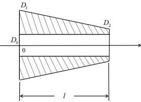
[0027] Specific implementation method: see attached figure 1 , the design method of a large-size annular conical ultrasonic horn, it is realized according to the following steps:

[0028] Step 1. The bus bar of the horn is selected as conical, and the vibration frequency is f, the longitudinal wave velocity is C, and the diameter of the large end is D 1 , the small end diameter is D 2 , the center hole diameter is D 0 , since the circular conical horn can be compared to the solid conical horn, so α, circular wave number k, and area coefficient N can be obtained as follows:

[0029]

[0030] in the known D 1 、D 2 、D 0 , f, C, you can find α, k, N and l.

[0031] The longitudinal wavelength λ is:

[0032]

[0033] When f and C are known, λ can be calculated.

[0034] Step 2. Substituting λ, k, and l obtained in step 1 into the resonance length formula (3) can obtain the resonance length L:

[0035]

[0036] Step 3. Substituting the k and α obtained in step 1 in...

Embodiment

[0044] The specific implementation will be further described below in conjunction with the examples, referring to the appended figure 1 , given D 1 =96mm,D 2 = 40mm, D 0 = 20mm, f = 20kHz, the material is No. 45 steel, then C = 5176376mm / s, get α = 0.00497, k = 0.0243, N = 3.8, l = 148.32mm, λ = 258.82mm.

[0045] Substitute the obtained λ, k, and l into the resonance length formula (3), and obtain the resonance length L=148.32mm.

[0046] Substitute the obtained k and α into the displacement node formula (4) to obtain the displacement node x 0 = 56.4 mm.

[0047] Substitute the obtained N, k and l into the amplification factor formula (5) to obtain the amplification factor M p = 3.74.

[0048] According to the obtained N, α, k and l, the shape factor can be obtained according to the formula (6)

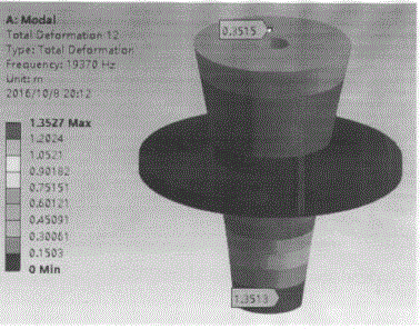
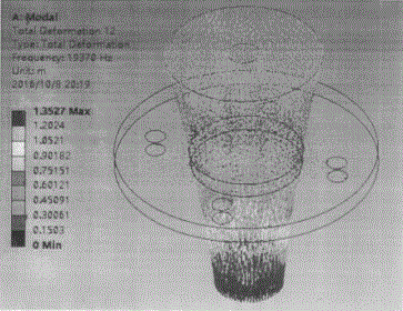
[0049] Use the simulation software to carry out numerical simulation based on the above given data and obtained results. The simulation results are shown in the attached f...


PUM


Abstract

The invention discloses a design method for a large-dimension annular cone type ultrasonic amplitude transformer, belongs to the design field of a power ultrasonic amplitude transformer, and solves the problems that the existing ultrasonic amplitude transformer adopts a solid structure mostly and is lack of an annular structure, and the amplification coefficient of the solid ultrasonic amplitude transformer is limited. The design method comprises the following steps of 1, calculating <alpha>, l, area coefficient N, circular wave number k and wavelength <lambda>; 2, calculating resonant length L; 3, calculating displacement node x<0>; 4, calculating the amplification coefficient M; 5, setting a strain maximum point x<M>, and further solving a shape factor <phi>; and 6, performing numerical value simulation by applying simulation software according to the set data and calculation results in the steps 1-5, and performing optimization on the design of the annular ultrasonic amplitude transformer. The design method is applicable to the design of the large-dimension annular cone type ultrasonic amplitude transformer.

Description

technical field [0001] The invention belongs to the field of power ultrasonic horn design, and in particular relates to a design method of a large-size annular conical ultrasonic horn. Background technique [0002] The ultrasonic horn is an important part of the ultrasonic vibration system. Its main function is to amplify the mechanical vibration displacement or velocity of the particle, and to concentrate the ultrasonic energy on a smaller area, that is, to gather energy. Ultrasonic horns mainly include stepped type, exponential type, conical type, hyperbolic type and other types. At present, most of the ultrasonic horns are of solid structure, and the amplification factor is limited. On this basis, in order to obtain a higher amplification factor, the only way to increase the diameter of the end face is to increase the diameter of the end face of the horn. If the diameter of the horn end face is too large, the radial vibration will increase. On the contrary, it will limit...

Claims


Application Information

Patent Timeline
Patent Type & Authority Applications(China)
IPC IPC(8): G06F17/50B06B1/10
CPCB06B1/10G06F30/20Y02T90/00
Inventor 高桂丽王傲许家勋陈国杰石德全
Owner HARBIN UNIV OF SCI & TECH
Features
  • R&D
  • Intellectual Property
  • Life Sciences
  • Materials
  • Tech Scout
  • Unparalleled Data Quality
  • Higher Quality Content
  • 60% Fewer Hallucinations
Learn More