Anti-seizing tool capable of avoiding drill clamping and reducing sticky slipping

A tool and stick-slip technology, which is applied in the direction of drill pipe, drill pipe, drilling equipment, etc., can solve the problems of drill bit mechanical penetration rate and rock breaking efficiency reduction, downhole drilling tool assembly damage, and drilling efficiency reduction, so as to improve drilling efficiency , prolong life, reduce stick-slip effect of drilling tools

Active Publication Date: 2017-04-19
沛县昌运机械制造有限公司
View PDF8 Cites 6 Cited by
  • Summary
  • Abstract
  • Description
  • Claims
  • Application Information

AI Technical Summary

Problems solved by technology

However, according to the situation at the mining site, it is shown that in the process of drilling ultra-deep wells, extended-reach wells, and horizontal wells, the PDC bit is prone to slippage during the drilling process, especially when encountering soft and hard formations, causing the bit and the drill bit to slip. The frequent jumping and torsional vibration of the tool will lead to chipping and damage of the drill bit, and damage to the downhole drilling tool assembly, which will reduce the mechanical penetration rate of the bit and the rock breaking efficiency, and increase the drilling cost
In order to deal with this phenomenon, most of the current drilling sites use the method of drilling to solve the phenomenon of drill sticking and drilling, because the drilling efficiency will be greatly reduced with the increase of the number of tripping

Method used


Image

  • Anti-seizing tool capable of avoiding drill clamping and reducing sticky slipping
  • Anti-seizing tool capable of avoiding drill clamping and reducing sticky slipping
  • Anti-seizing tool capable of avoiding drill clamping and reducing sticky slipping

Examples


Embodiment Construction

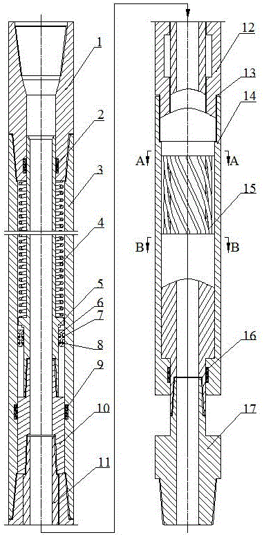
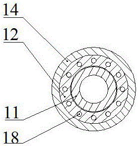
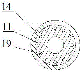
[0019] According to the drawings, the anti-stagnation tool for avoiding sticking and reducing stick-slip is mainly composed of upper joint 1, upper housing 3, adapter 12, lower housing 14, dynamic sealing ring a2, dynamic sealing ring b9, Dynamic sealing ring c16, compression spring 4, compression spring guide rod 5, floating sealing ring 6-8, anti-drop joint 10, mandrel 11, O-shaped sealing ring 13, steel wire rope 15, mandrel joint 17; it is characterized in that, The upper joint 1, the upper housing 3, the adapter 12, and the lower housing 14 are sequentially connected by threads to form the shell of the tool. There is an O-ring 13 at the threaded connection between the adapter 12 and the lower housing 3; Among them, the compression spring 4 is installed on the compression spring guide rod 5, and the axial positioning is carried out through the lower end of the upper joint 1 and the shoulder of the compression spring guide rod 5; The seal ring a2, the dynamic seal ring a2 i...


PUM


Abstract

The invention discloses an anti-seizing tool capable of avoiding drill clamping and reducing sticky slipping to solve the problem that the rock breaking efficiency is low due to clamping and slipping in the drilling process. According to the main technical scheme, an upper connector, an upper shell, an adapter and a lower shell are sequentially connected through a thread; a compression spring is mounted on a compression spring guide rod, the low end of the compression spring guide rod pushes an anti-falling connector to enable a mandrel to stretch, and the anti-falling connector is connected with a mandrel thread and axially positioned through an adapter shaft shoulder; a steel wire rope system is arranged in a left-rotation mode, the upper and lower ends of the steel wire rope system are separately fixed to the lower end of the adapter and fixed into a circular groove in the upper end of a mandrel boss, the upper and lower ends of steel wire ropes are mounted by 30-40 degrees in an inclined mode, and the steel wire ropes are in a tensional state initially; during work, drilling pressure is transferred to the mandrel through the compression spring, and torque is transferred to the mandrel through the steel wire rope system; and when the mandrel rotates backwards, the steel wire rope system retracts to enable the mandrel to compress the compression spring to axially retract so as to decrease the cutting depth of a drill bit, and the drill bit is in a rock mass in the whole process.

Description

technical field [0001] The invention relates to an anti-sluggish tool for avoiding sticking and reducing stick-slip used in the fields of oil and natural gas ultra-deep wells and extended-displacement drilling. Background technique [0002] In recent years, with the continuous development of my country's industry, the demand and extraction of oil and natural gas are also increasing. However, this situation has led to the depletion of a large number of shallow oil and gas resources. In order to alleviate the shortage of oil resources in our country, people began to exploit oil in areas with severe environmental conditions such as deep wells and ultra-deep wells. However, according to the situation at the mining site, it is shown that in the process of drilling ultra-deep wells, extended-reach wells, and horizontal wells, the PDC bit is prone to slippage during the drilling process, especially when encountering soft and hard formations, causing the bit and the drill bit to sl...

Claims


Application Information

Patent Timeline
Patent Type & Authority Applications(China)
IPC IPC(8): E21B17/07
CPCE21B17/07
Inventor 田家林袁长福杨琳杨应林吴纯明刘刚杨志吴波
Owner 沛县昌运机械制造有限公司
Why Eureka
Try Eureka