Thermal management system and method of cuboid battery pack

A thermal management system and cuboid technology, applied in the field of thermal management, can solve the problems of low protection level of the battery box, weak ability to prevent thermal runaway, poor temperature uniformity of the battery, etc., to reduce interface contact resistance, increase heat dissipation contact area, and uniform temperature Effect

Active Publication Date: 2017-04-19
赵耀华
View PDF8 Cites 6 Cited by
  • Summary
  • Abstract
  • Description
  • Claims
  • Application Information

AI Technical Summary

Problems solved by technology

[0003] The present invention aims at the poor heat dissipation effect, poor battery temperature uniformity, weak ability to prevent thermal runaway, independent high-temperature heat dissipation and low-temperature heating systems (that is, dual systems), large system volume and high cost in the existing vehicle-mounted battery thermal management system As well as the low protection level of the battery box, a new type of thermal management system for rectangular parallelepiped battery packs is provided. Through the micro heat pipe array plate and high-efficiency heat exchange elements, it exchanges heat quickly and efficiently with the rectangular parallelepiped battery, ensuring efficient heat dissipation of the rectangular parallelepiped battery and uniform battery temperature. And at the same time realize efficient low-temperature heating function, at the same time, the thermal management system is compact, light in weight, and low in cost, and the battery pack box can achieve high-level protection

Method used


Image

  • Thermal management system and method of cuboid battery pack
  • Thermal management system and method of cuboid battery pack
  • Thermal management system and method of cuboid battery pack

Examples


Embodiment Construction

[0037] The present invention will be described below in conjunction with the accompanying drawings.

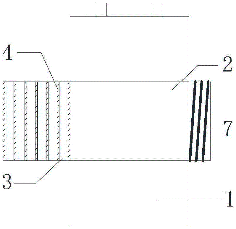
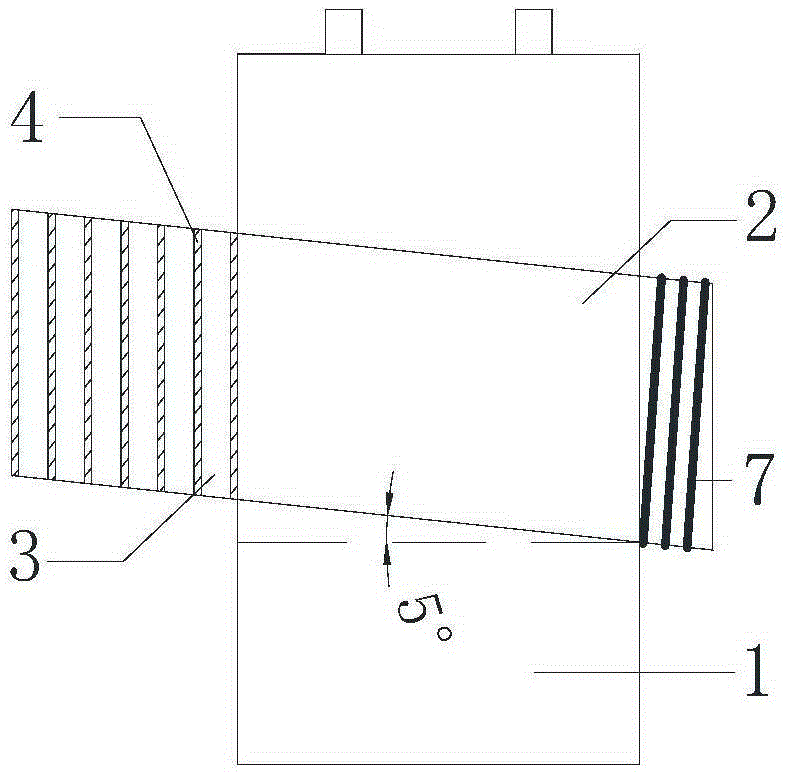
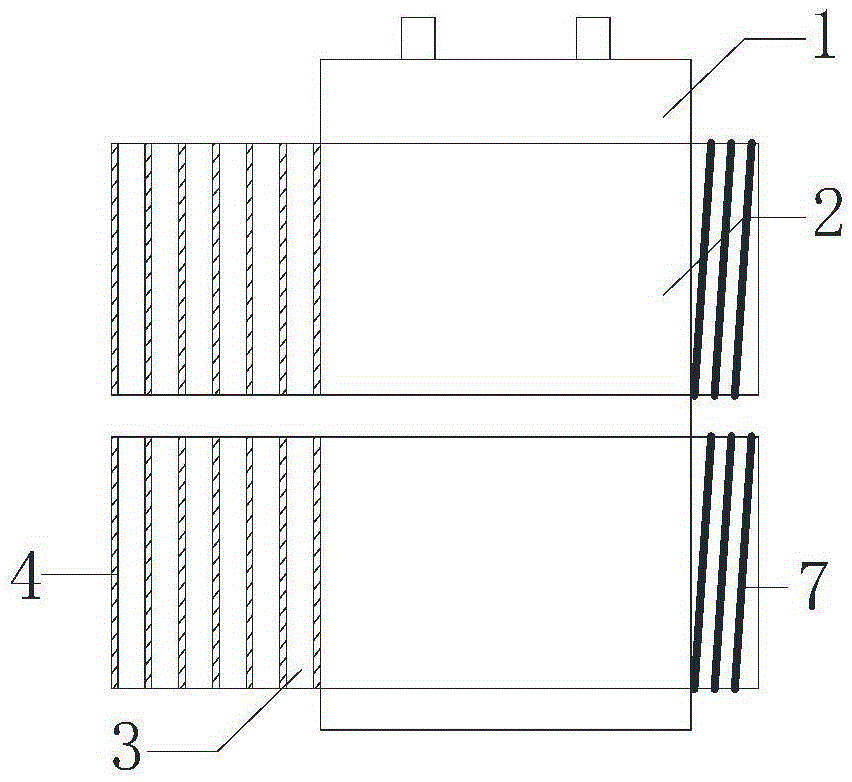
[0038] The present invention relates to a thermal management system for a rectangular parallelepiped battery pack on an electric vehicle, comprising a micro heat pipe array plate, a heat exchange element (preferably a heat sink or a heat exchanger) and a heat source, wherein the heat source can be an electric heating element or The heated fluid medium (it can be a hot fluid medium with a temperature higher than the battery temperature, such as hot air or hot liquid) pipeline, the electric heating element can be a resistance wire or an electric heating film; the micro heat pipe array plate is extruded from a metal material It has a plate-like structure with more than two micro heat pipe arrays arranged side by side. The equivalent diameter of each micro heat pipe in the micro heat pipe array is 0.2mm-2.5mm. The section is attached to the battery plate surface of the rectangular...


PUM

PropertyMeasurementUnit
Thicknessaaaaaaaaaa

Abstract

The invention relates to a thermal management system and a method of a cuboid battery pack. The thermal management system comprises a micro heat pipe array plate, a heat exchanger component, and a heat source; in heat radiation, an evaporation section of the micro heat pipe array plate is designed to attach to a battery panel surface of the cuboid battery pack, a condensation section of the micro heat pipe array plate is designed to stretch out the side surface of the cuboid battery pack; the heat exchanger component is arranged on the condensation section of the micro heat pipe array plate, heat pipe effect is achieved after absorption of heat energy of the cuboid battery pack by the evaporation section of the micro heat pipe array plate, and heat exchange with the outside environment is realized via the condensation section of the micro heat pipe array plate; in preheating, the heat source is arranged on the evaporation section of the micro heat pipe array plate, the condensation section of the micro heat pipe array plate is designed to attach to the battery panel surface of the cuboid battery pack, heat pipe effect is achieved after absorption of heat energy of the heat source by the evaporation section of the micro heat pipe array plate, and heat release to the cuboid battery pack is realized via the condensation section of the micro heat pipe array plate. According to the thermal management system, combination of heat dissipation and heating functions is realized, and heat exchange efficiency is increased.

Description

technical field [0001] The invention relates to the technical field of thermal management, in particular to a thermal management system and method using a micro heat pipe array plate for a rectangular parallelepiped battery pack. Background technique [0002] As the future of the automobile industry, electric vehicles powered by on-board batteries (storage batteries / lithium batteries) have been valued and developed for their advantages of low pollution, energy saving, and high thermal efficiency. Electric vehicles use electric energy instead of conventional fossil fuels such as petroleum as power, which has obvious environmental protection advantages and is a long-term solution suitable for the field of future transportation tools. As the key technology of electric vehicle power, on-board battery will accumulate a lot of heat in the process of high-current charging and discharging. If the heat is not removed in time, the temperature of the battery will rise sharply, especial...

Claims


Application Information

Patent Timeline
IPC IPC(8): H01M10/61H01M10/617H01M10/635H01M10/6552H01M10/625
CPCY02E60/10
Inventor 赵耀华叶欣张楷荣
Owner 赵耀华
Why Eureka
Try Eureka