
Downhole degassing and oil removing cyclone separation device

A cyclone separation device and degassing technology, which is applied in the direction of the cyclone device, the device whose axial direction can be reversed, liquid separation, etc., can solve the problem of poor separation effect, inability to achieve high-efficiency oil-water separation, low separation efficiency, etc. problems, to achieve the effect of convenient installation, good degassing and degreasing function, and high separation efficiency

Active Publication Date: 2017-04-26
NORTHEAST GASOLINEEUM UNIV
View PDF10 Cites 23 Cited by
  • Summary
  • Abstract
  • Description
  • Claims
  • Application Information

AI Technical Summary

Problems solved by technology

[0003] In order to solve the problems that the oil-water separation equipment used in the current downhole oil-water separation process has poor separation effect and low separation efficiency under gas-containing conditions, and cannot achieve high-efficiency separation of oil-water phases under gas-containing conditions, this invention has passed the national 863 project: Supported by downhole oil-water separation and same-well reinjection technology and equipment funds, a downhole degassing and deoiling cyclone separation device is provided. This kind of downhole degassing and deoiling cyclone separation device can realize efficient degassing and deoiling downhole , can enhance the applicability of separation equipment to gas-bearing conditions, and is of great significance to enhance the applicability of downhole oil-water separation and same-well reinjection system and make it operate efficiently for a long time

Method used


Image

  • Downhole degassing and oil removing cyclone separation device
  • Downhole degassing and oil removing cyclone separation device
  • Downhole degassing and oil removing cyclone separation device

Examples


Embodiment Construction

[0039] The present invention will be further described below in conjunction with accompanying drawing:

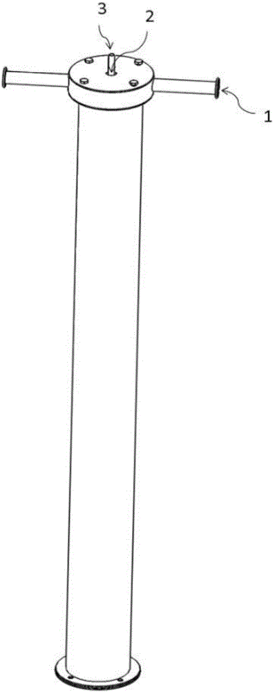
[0040] This new type of downhole degassing and oil removal cyclone separation method and the overall appearance of the device are as follows figure 1 shown. figure 2 is the axial cross-sectional view of the device, image 3 It shows the internal structure of the device. The invention is mainly composed of two parts: an external gas-liquid separation chamber and an internal secondary oil-water separation chamber, and also includes some devices such as a gas-liquid isolation pipe, an inlet device, and a variable-diameter separation pipe. The external gas-liquid separation chamber is mainly used to realize the gas-liquid separation treatment of the incoming liquid. Through the diversion hole at the bottom of the separation chamber, the treatment liquid that removes the gas phase is introduced into the oil-water separation chamber. Stage oil-water separation, and then oil, ...


PUM


Abstract

The invention discloses a downhole degassing and oil removing cyclone separation device and mainly aims to solve the problem that the downhole oil-water separation effect is limited due to existence of associated gas. The device is characterized in that the cyclone separation device adopts a twin-tangential inlet, so that the tangential and radial pressure required when a to-be-treated liquid is subjected to first-stage degassing separation is guaranteed, meanwhile, a first-stage degassing separation structure is separated from an oil removing separation structure through a barrel, and two stages of separation communicate with each other through hole opening in proper positions; the degassed treated liquid is pressurized and accelerated by a pressurizing part, and thus separation is conducted efficiently; and an oil-water separation structure adopts the two-stage pressurization and two-stage separation manners, and accordingly, the oil-water separation accuracy is improved. With the device, the downhole oil-water separation efficiency can be improved, and the feasibility and the applicability of the downhole oil-water separation system can be enhanced.

Description

technical field [0001] The invention relates to a separation device used in the fields of petroleum, chemical industry, etc., specifically, a separation device used in the separation of oilfield production fluid and sewage treatment. Background technique [0002] With the continuous development of oilfields, the development of many onshore oilfields has entered the middle and later stages, and the water content of oil wells is getting higher and higher, and the water content of many oil wells is greater than 95%. Therefore, how to deal with the produced water is a difficult problem that many oilfields have to face. With the in-depth research, a complete set of downhole oil-water separation and same-well reinjection technology scheme with cyclone equipment as the main separation part has basically been formed. The cyclone separator used for oil-water separation shows good separation performance in the downhole environment. Effect. However, the separation effect is limited du...

Claims


Application Information

Patent Timeline
IPC IPC(8): B04C5/08B04C5/081B04C5/103C02F1/40C02F1/38C02F103/10
CPCB04C5/08B04C5/081B04C5/103C02F1/38C02F1/40C02F2103/10
Inventor 张勇蒋明虎赵立新李枫邢雷
Owner NORTHEAST GASOLINEEUM UNIV
Learn More