
Hole-edge crack diagnosis method based on optical fiber spectrum image analysis

A technology of image analysis and optical fiber spectroscopy, applied in the field of hole edge crack diagnosis, which can solve the problems of missed detection and false alarms of intelligent coating sensors, statistical models that do not explain the relationship between crack propagation and reflection spectrum, and characteristic parameters that have no physical meaning.

Inactive Publication Date: 2017-04-26
BEIHANG UNIV
View PDF5 Cites 6 Cited by
  • Summary
  • Abstract
  • Description
  • Claims
  • Application Information

AI Technical Summary

Problems solved by technology

[0003] In the relevant literature and experiments, it is found that for the qualitative problem of the presence or absence of cracks in the process of crack propagation at the edge of the aluminum alloy plate hole, the smart coating sensor will have missed detection and false alarms during monitoring, and the fiber grating sensors currently used are mostly Establish the relationship between strain and crack length, and the extracted characteristic parameters are mostly statistical models without physical meaning, and do not explain the relationship between crack growth and reflection spectrum from the perspective of optical properties itself

Method used


Image

  • Hole-edge crack diagnosis method based on optical fiber spectrum image analysis
  • Hole-edge crack diagnosis method based on optical fiber spectrum image analysis
  • Hole-edge crack diagnosis method based on optical fiber spectrum image analysis

Examples


Embodiment Construction

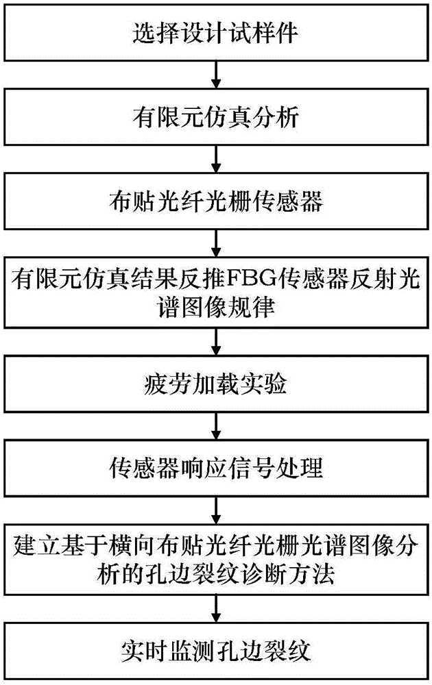
[0033] The present invention will be further described in detail with reference to the accompanying drawings and embodiments. The invention provides a method for diagnosing cracks at the edge of a hole based on optical fiber spectral image analysis. The overall process schematic diagram of the method is as follows figure 2 shown.

[0034] A method for diagnosing cracks at the edge of a hole based on optical fiber spectral image analysis of the present invention, see figure 1 , 2 As shown, it is realized through the following steps:

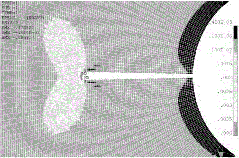
[0035] The first step is to select the sample aluminum alloy sheet such as image 3 As shown, its brand specification: aluminum alloy 2024-T3, 300*100*2 (mm). In order to appear fatigue crack growth faster, a circular hole with a diameter of Φ10mm is opened in the center of the aluminum alloy sheet, and a small crack with a length of 3mm is prefabricated on the right side of the hole parallel to the short axis.

[0036]The second step is to ...


PUM


Abstract

A hole-edge crack diagnosis method based on optical fiber spectrum image analysis includes the following steps: (1) selecting a test sample and designing the test sample; (2) performing structural mechanics analysis to the test sample; (3) pasting fiber Bragg grating sensors on an aluminum alloy thin board; (4) according to finite element simulation results, backstepping the principle of a reflective spectrum image of the FBG sensors; (5) installing the aluminum alloy thin board, on which the FBG sensors are pasted, on a fatigue test machine to perform fatigue crack propagation test; (6) processing signals collected by the FBG sensors; and (7) repeating the steps (1) - (5) to verify the method established in the step (6); and (8) completing real-time monitoring of the cracks. By means of the steps, the hole-edge crack diagnosis method based on transversal-arranged FBG spectrum analysis is achieved, thereby achieving the researching effect of diagnosis on length of a hole-edge crack. The method solves the positioning problem of length of the hole-edge crack in the aluminum alloy board in engineering application.

Description

technical field [0001] The invention provides a hole edge crack diagnosis method based on optical fiber spectral image analysis, which is applied to the fatigue crack monitoring problem of metal plates, and specifically relates to a method for monitoring the fatigue crack growth of aluminum alloy thin plates by using the spectral characteristics of optical fiber grating sensors , which belongs to the field of structural health monitoring. Background technique [0002] Structural health monitoring is a technology that uses advanced smart sensors to monitor the health of structures in real time. Compared with traditional non-destructive testing technology, it is more efficient and more targeted, so it is widely used in the aerospace field. Fatigue cracks are a typical damage of metal structures, if effective monitoring cannot be carried out in the initial stage of crack initiation and propagation process, it will cause serious consequences. At present, using structural health...

Claims


Application Information

Patent Timeline
IPC IPC(8): G01N3/06
CPCG01N3/068G01N2203/0066G01N2203/0073G01N2203/0647G01N2203/0682
Inventor 张卫方张萌金博李英武任飞飞刘晓鹏梁小贝魏巍高晓岩
Owner BEIHANG UNIV
Learn More