
Radar video linkage based intelligent boundary security system

A security protection and video linkage technology, applied in CCTV systems, televisions, burglar alarms, etc., can solve the problems of weather and light, reduce equipment installation, and high false alarm rate, and achieve high radar resolution and adjustment speed. Fast, penetrating effect

Inactive Publication Date: 2017-04-26
秦皇岛博微智能科技有限公司
View PDF0 Cites 29 Cited by
  • Summary
  • Abstract
  • Description
  • Claims
  • Application Information

AI Technical Summary

Problems solved by technology

[0006] The main defects of the closed-circuit television monitoring system are: real-time detection cannot be achieved, and the video is usually retrieved afterwards to trace clues; therefore, the intrusion point cannot be actively located, the detection range is small, and it is greatly affected by weather and light; the reliability of the alarm algorithm is low
[0009] 1. The false alarm rate is high, birds, insects, falling leaves, swinging branches, etc. may cause false alarms;
[0010] 2. The protection range is small
Due to the straight-line propagation characteristics of infrared / laser, light-based security systems can only establish a very limited detection area, which is easily crossed by intruders;
[0011] 3. No ranging capability
[0017] The invention is used to overcome the defects of the traditional perimeter system, not only can obtain the accurate position of the alarm information, but also can mobilize the numerical control linkage ball machine to track the target; a single device can monitor the area range of 300 meters, reducing the installation of equipment; solve Eliminates the high rate of false alarms or failure of traditional perimeter security technologies in severe weather conditions such as heavy fog and strong winds

Method used


Image

  • Radar video linkage based intelligent boundary security system
  • Radar video linkage based intelligent boundary security system

Examples


Embodiment Construction

[0041]Below in conjunction with accompanying drawing and specific embodiment the present invention is described in further detail:

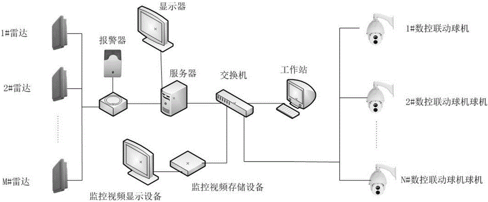
[0042] A radar video linkage intelligent perimeter safety protection system of the present invention, its system topology diagram is as follows figure 1 As shown, the system includes radar, CNC linkage dome machine, server, switch, workstation, surveillance video storage device, surveillance video display device and alarm device;

[0043] In specific implementation, the system can be applied to the perimeter of places with high security levels such as factories, airports, substations, and important material warehouses. The standard version of the system uses 4 radars and 4 CNC linkage ball machines for linkage. The warning range of each radar is a wall. The CNC linkage ball machines used for linkage are installed on poles near the wall, or directly installed on On the top of the house, as long as the fence is within the visible range of the CNC ...


PUM


Abstract

The invention discloses a radar video linkage based intelligent boundary security system which comprises a radar, a numerical control linkage ball device, a server, a switchboard, a workstation, a monitoring video storage device, a monitoring video display device and an alarming device, wherein the server is connected with the radar through an RS485 bus; intelligent boundary security system software is installed on the server; the control on the three-dimensional linkage of the radar and the numerical control linkage ball device is the core of the software; the numerical control linkage ball device, the server, the workstation, the monitoring video storage device, the monitoring video display device and the alarming device are connected with a same local area network through cables; the numerical control linkage ball device is connected with the local area network through a photo-electric converter and an optical fiber. The radar video linkage based intelligent boundary security system has the beneficial effects of active detection, intelligent identification, locating and tracking, low false report, short construction period and high adjusting speed.

Description

technical field [0001] The invention relates to a security system, in particular to a radar video linkage intelligent perimeter security system. Background technique [0002] The perimeter alarm system is an alarm system, which is an alarm trigger system composed of perimeter alarm detectors, alarm hosts, and transmission media. In recent years, as people pay more attention to their own personal and property safety, perimeter alarm, as an integral part of security alarm, has also been valued by the majority of security engineering companies and end users, and more and more people pay attention to perimeter alarms. The principle of the perimeter alarm is mostly: the front end of the detector senses the alarm information, if someone invades and triggers the alarm, the perimeter alarm detector will transmit the detected alarm signal to the alarm host, and the alarm host will send an alarm through the linkage device or sound The device prompts the front-end alarm. [0003] The...

Claims


Application Information

Patent Timeline
IPC IPC(8): G08B13/181H04N7/18
CPCG08B13/181H04N7/188
Inventor 肖猛胡振鹏朱德良
Owner 秦皇岛博微智能科技有限公司
Learn More