Large power high efficiency thermal equilibrium LLC resonant converter and control method thereof

A resonant converter, heat balance technology, applied in the direction of converting DC power input to DC power output, high-efficiency power electronic conversion, output power conversion device, etc. , loss and increase in the volume of magnetic core components, to achieve the effect of facilitating thermal design, increasing gain, and improving output accuracy

Inactive Publication Date: 2017-04-26
深圳朗兴智能云充有限公司
View PDF4 Cites 15 Cited by
  • Summary
  • Abstract
  • Description
  • Claims
  • Application Information

AI Technical Summary

Problems solved by technology

[0003] Under the rated operating conditions of LLC, the resonant circuit can work near the resonant frequency. At this time, the efficiency of the resonant converter is the highest, but when the input or output voltage changes, it needs to adjust the frequency to adapt to this voltage change. With the frequency shift, the circuit The loss will increase and the system efficiency will decrease. The resonant inductor and transformer will have difficulty in heat dissipation due to the increase of copper loss and magnetic loss, especially when the output of the LLC converter is under high-voltage light load and low-voltage heavy load, the resonant inductor and transformer are prone to thermal imbalance. , and the solution to the heat dissipation problem can only be solved by increasing the window area of ​​the magnetic core and incre

Method used


Image

  • Large power high efficiency thermal equilibrium LLC resonant converter and control method thereof
  • Large power high efficiency thermal equilibrium LLC resonant converter and control method thereof
  • Large power high efficiency thermal equilibrium LLC resonant converter and control method thereof

Examples


Embodiment Construction

[0028] The present invention will be further described in detail below in conjunction with the accompanying drawings. It is necessary to point out that the following specific embodiments are only used to further illustrate the present invention and cannot be understood as limiting the scope of protection of the present invention. Those skilled in the art can follow The above content of the invention makes some non-essential improvements and adjustments to the invention.

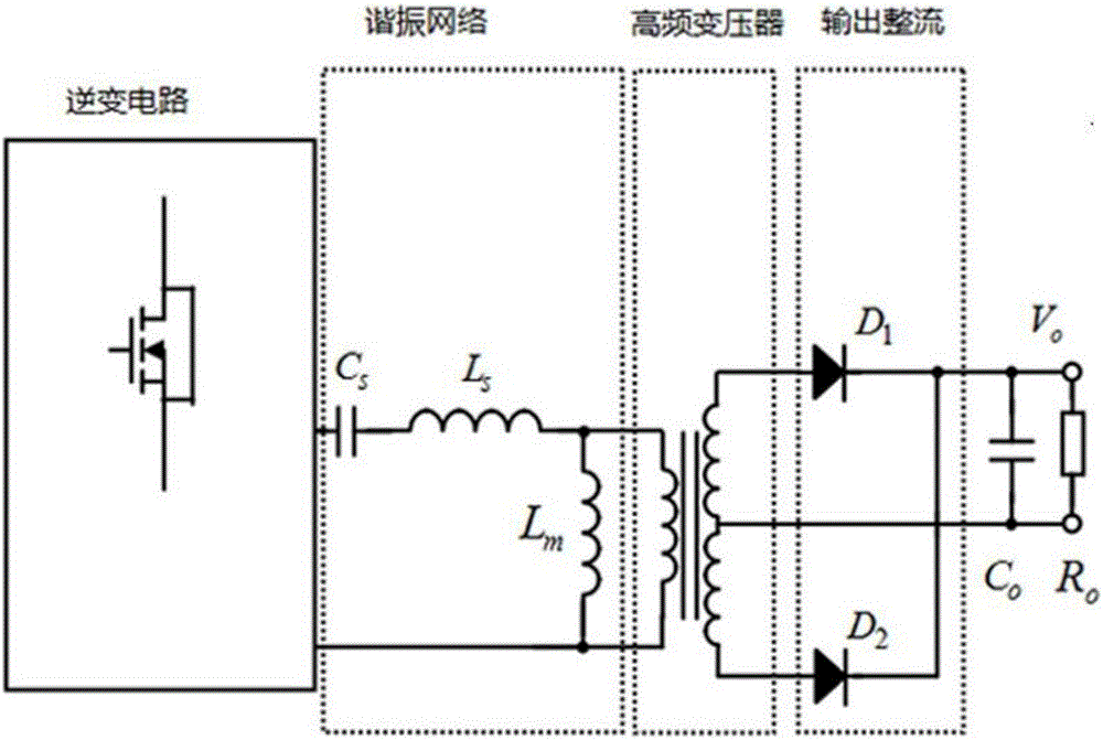
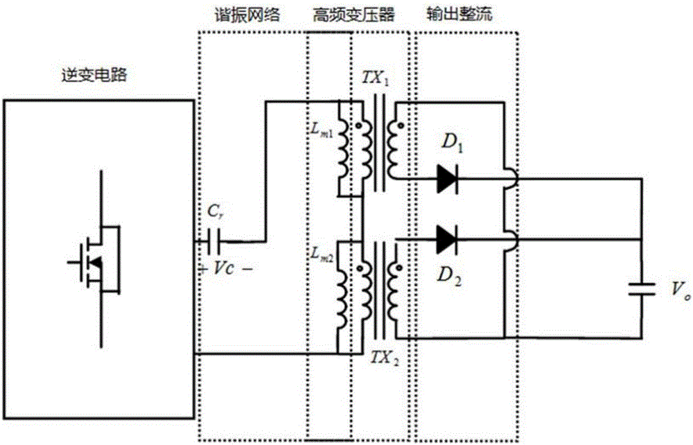
[0029] Such as figure 2 As shown, the improved LLC resonant converter of this application includes an inverter circuit, a resonant network, a high-frequency transformer, and an output rectifier circuit. The high-frequency transformer is composed of 2n transformers, and the primary windings of the 2n transformers are connected in series. , The secondary winding is connected in parallel and then connected to the output rectifier circuit, the primary winding is connected in parallel with the excitation inductance, ...


PUM


Abstract

The invention relates to a large power high efficiency thermal equilibrium LLC resonant converter and a control method thereof. The large power high efficiency thermal equilibrium LLC resonant converter comprises an inversion circuit, a resonant network, high frequency transformers, and an output rectification circuit. The high frequency transformer is constituted by 2n transformers, and the primary windings of the 2n transformers are serially connected together, and the secondary windings of the 2n transformers are parallely connected together, and then are connected with the output rectification circuit. The primary windings are parallely connected with excitation inductors, and the resonant network is constituted by resonant capacitors, the primary excitation inductor of the2n-1th transformer, and the primary excitation inductor of the 2nth high frequency transformer, which are serially connected together. The resonant converter works in six working modes in a switching period. The high frequency transformers are used to replace the resonant inductors, and then the high frequency transformers are used as the resonant inductors, and are also used as the excitation inductors and the transformers, and therefore material costs are saved, output ripple, output precision, and other performances are greatly improved.

Description

Technical field [0001] This application relates to an LLC resonant converter, in particular to a high-power and high-efficiency thermally balanced LLC resonant converter and a control method thereof. Background technique [0002] LLC resonant converter is a kind of soft switching. It uses fewer components to realize zero voltage turn-on of the primary side switch tube and zero current turn-off of the secondary side diode, thereby achieving lower switching losses. Such as figure 1 As shown, the LLC resonant converter includes an inverter circuit, a resonance circuit, a high-frequency transformer, and a rectifier circuit; the inverter circuit can be a two-level or three-level asymmetric half-bridge circuit and a full-bridge circuit; the resonance circuit is composed of The resonant capacitor, the resonant inductance and the primary inductance of the high frequency transformer are connected in series. When working, the inverter circuit outputs a complementary level with a fixed 50%...

Claims


Application Information

Patent Timeline
IPC IPC(8): H02M3/335
CPCH02M3/33523Y02B70/10
Inventor 邓彦彦梁一龙王瑞冬陈奕坚陈志雄
Owner 深圳朗兴智能云充有限公司
Why Eureka
Try Eureka