
A catalytic conversion method for increasing production of low-carbon olefins and producing high-quality gasoline

A catalytic conversion method and technology for low-carbon olefins, which are applied in the directions of catalytic cracking, treatment of hydrocarbon oil, and hydrocarbon oil treatment products, etc., can solve the problems such as the inability to guarantee the directness and the satisfactory output, and achieve low octane number and alkane content. high effect

Active Publication Date: 2018-07-31
CHINA PETROLEUM & CHEM CORP +1
View PDF7 Cites 0 Cited by
  • Summary
  • Abstract
  • Description
  • Claims
  • Application Information

AI Technical Summary

Problems solved by technology

[0006] To sum up, from the perspective of the existing catalytic cracking technology to increase the production of low-carbon olefins, all or part of the secondary cracking of gasoline fractions is provided by using catalysts containing shape-selective molecules or mesoporous zeolites to recycle gasoline fractions. To achieve the purpose of increasing the production of propylene, but these technologies were developed before the official promulgation of the motor gasoline standard GB17930-2013, and the actual technology cannot be beneficial to ensure that the direct output meets the requirements of GB17930-2013 that the olefin content is not more than 24% (volume fraction), aromatics content not greater than 40% (volume fraction), benzene content not greater than 1.0% (volume fraction) of the technical requirements of high-octane gasoline

Method used


Image

  • A catalytic conversion method for increasing production of low-carbon olefins and producing high-quality gasoline
  • A catalytic conversion method for increasing production of low-carbon olefins and producing high-quality gasoline
  • A catalytic conversion method for increasing production of low-carbon olefins and producing high-quality gasoline

Examples


Embodiment 1

[0080] This example is used to illustrate the catalytic conversion method for increasing the production of light olefins and producing high-quality gasoline provided by the present invention.

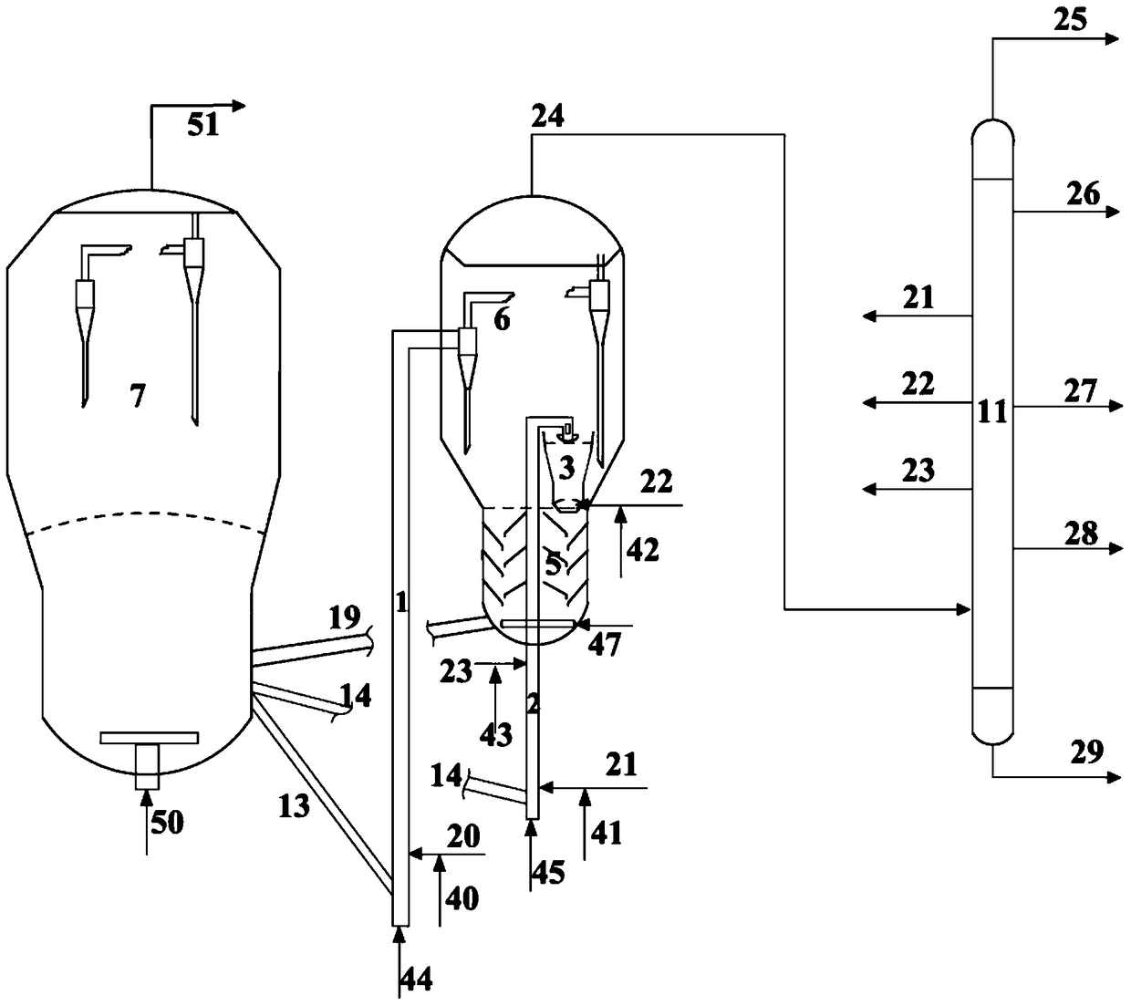
[0081] Experiments were carried out with a medium-sized plant for continuous reaction-regeneration operation with three reactors, the first reactor being a riser, the riser reactor having an inner diameter of 16 mm and a height of 3800 mm. The second reactor was a riser reactor with an inner diameter of 16 mm and a height of 3200 mm. The outlet of the second riser reactor was introduced into the fluidized bed reactor, the inner diameter of the fluidized bed reactor was 64 mm, and the height was 300 mm.

[0082] The regenerated catalyst with a temperature of about 700°C enters the bottom of the riser reactor of the first reactor through the inclined pipe of the regenerated catalyst, and flows upward under the action of the pre-lift steam. Heavy hydrocarbon oil feedstock (see Table 2 for...

Embodiment 2

[0084] This example is used to illustrate the catalytic conversion method for increasing the production of light olefins and producing high-quality gasoline provided by the present invention.

[0085] The reaction apparatus that adopts is with embodiment 1. Raw material, main experimental procedure are the same as embodiment 1, and difference is that the raw material nozzle at the bottom of the second reactor riser is the starting point, and the effective length of the riser is defined as 100% along the flow direction of the raw material, and the light end fraction ( Distillation range is the initial boiling point ~ 57 ℃) into the starting point of the second riser, and the heavy fraction (distillation range is 178 ℃ ~ 253 ℃) enters 70% of the downstream of the light fraction (that is, the injection of the heavy fraction) position to the length of the reactor outlet is 30%), and the selected middle distillate fractionation range is 57~178°C. The main operating conditions and ...

Embodiment 3

[0092] This example is used to illustrate the catalytic conversion method for increasing the production of light olefins and producing high-quality gasoline provided by the present invention.

[0093] The reaction apparatus that adopts is with embodiment 1.

[0094] The regenerated catalyst with a temperature of about 650°C enters the bottom of the riser reactor of the first reactor through the inclined pipe of the regenerated catalyst, and flows upward under the action of the pre-lift steam. Heavy hydrocarbon oil feedstock (see Table 2 for main properties) is heated to about 350°C in a preheating furnace, mixed with atomized water vapor, sprayed into the first reactor through the feed nozzle, and catalyzed by contact with the hot regenerated catalyst conversion reaction. The reaction oil gas and the catalyst to be produced enter the settler from the outlet of the riser of the first reactor for rapid separation, and the reaction oil gas is further separated into gas products ...


PUM

PropertyMeasurementUnit
The inside diameter ofaaaaaaaaaa
Heightaaaaaaaaaa
Heightaaaaaaaaaa

Abstract

The invention relates to the catalytic cracking field of heavy hydrocarbon gasoline raw materials and particularly discloses a catalytic converting method for increasing the yield of low-carbon olefins and producing high-quality gasoline. The method comprises the following steps: 1, enabling a heavy hydrocarbon gasoline raw material to carry out contact reaction with a first catalytic cracking catalyst in a first reactor; 2, injecting a light distillate component of which the boiling point is 8-88DEG C into a second reactor, enabling the light distillate component to carry out contact reaction with a second catalytic cracking catalyst, injecting a heavy distillate component of which the boiling point is 145-253DEG C into the second reactor from the downstream of the light distillate component, and after reaction, obtaining a second reaction mixture; and 3, injecting a medium distillate component of which the boiling point is 41-190DEG C into a third reactor, and enabling the medium distillate component to carry out contact reaction with a solid catalyst separated from the second reaction mixture. The method provided by the invention can increase the yield of the low-carbon olefins and prepare the high-quality gasoline.

Description

technical field [0001] The invention relates to the field of catalytic cracking of heavy hydrocarbon oil raw materials, in particular to a catalytic conversion method for increasing the production of light olefins and producing high-quality gasoline. Background technique [0002] In recent years, the rapid growth of global propylene demand has made increasing propylene production an important technical trend in the field of petroleum refining. Even more stringent, it is required that the content of olefins is not more than 24% (volume fraction), the content of aromatics is not more than 40% (volume fraction), and the content of benzene is not more than 1.0% (volume fraction). As crude oil becomes heavier, the supply of light petroleum hydrocarbons is limited. Using traditional heavy oil catalytic cracking technology as a platform, using cheap heavy oil as raw material, and strengthening the deep catalytic cracking reaction of heavy hydrocarbons to produce more propylene, and...

Claims


Application Information

Patent Timeline
IPC IPC(8): C10G11/02C10G11/14C10G11/18
CPCC10G11/02C10G11/14C10G11/18C10G11/182C10G2300/1037C10G2300/104C10G2300/1044C10G2300/1051C10G2300/1055C10G2400/02C10G2400/20
Inventor 朱金泉崔琰杨轶男谢朝钢高永灿
Owner CHINA PETROLEUM & CHEM CORP
Features
  • Generate Ideas
  • Intellectual Property
  • Life Sciences
  • Materials
  • Tech Scout
  • Unparalleled Data Quality
  • Higher Quality Content
  • 60% Fewer Hallucinations
Learn More