
System, method and device for measuring neurocranium pressure

A cranial and ventricle technology, applied in the system field of measuring intracranial pressure, can solve the problems of high infection risk, high measurement cost, and inability to achieve continuous measurement, so as to reduce the risk of infection and the pain of patients

Inactive Publication Date: 2017-05-10
HARBIN INST OF TECH SHENZHEN GRADUATE SCHOOL
View PDF6 Cites 0 Cited by
  • Summary
  • Abstract
  • Description
  • Claims
  • Application Information

AI Technical Summary

Problems solved by technology

The former mainly uses CT or MRI images to judge whether the intracranial pressure has increased, and accurate measurement values ​​cannot be obtained, and this method requires the patient to be brought to a special device, requiring the patient to be stable, continuous measurement cannot be achieved, and the measurement cost is high; the latter It can also be divided into wired and wireless measurements. In the wired intracranial pressure measurement method, there is a method known as the gold standard for intracranial pressure measurement. Specifically, a catheter is connected (or lumbar puncture) in the ventricle, and then the cerebrospinal fluid is drained. To the pressure transducer, the measured intracranial pressure is obtained. This method is more accurate in measuring the structure and is convenient for zero-point detection, but the patient's activities are restricted and there is a high risk of infection.

Method used


Image

  • System, method and device for measuring neurocranium pressure
  • System, method and device for measuring neurocranium pressure
  • System, method and device for measuring neurocranium pressure

Examples


Embodiment 1

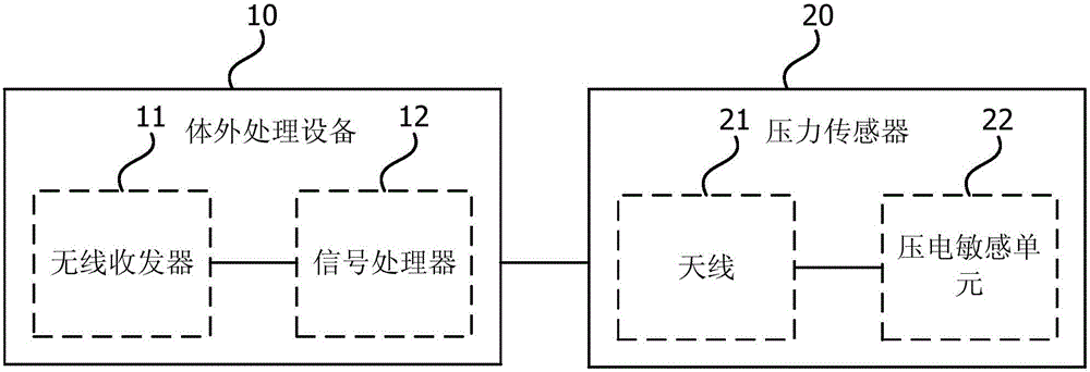
[0042] figure 1 It is a schematic structural diagram of a system for measuring intracranial pressure provided by Embodiment 1 of the present invention. The system for measuring intracranial pressure can be integrated into any device with the function of measuring intracranial pressure. Wireless passive and continuous measurement of pressure. The system includes: an extracorporeal treatment device 10 and a pressure sensor 20 .

[0043] Wherein, the extracorporeal processing device 10 includes a wireless transceiver 11 and a signal processor 12; the wireless transceiver 11 is used to transmit a wireless excitation signal to the pressure sensor 20, and receive a wireless detection signal generated by the pressure sensor 20 according to intracranial pressure; the signal processor 12 is connected with the wireless transceiver 11, and is used to control the wireless transceiver 11 to transmit the wireless excitation signal and calculate the intracranial pressure according to the wi...

Embodiment 2

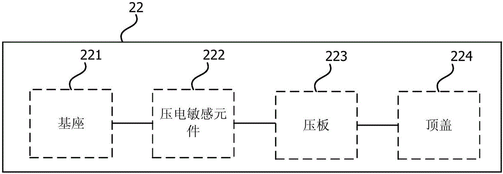
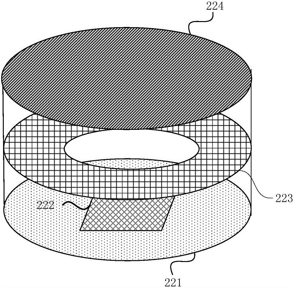
[0059] Figure 4 It is a flowchart of a method for measuring intracranial pressure provided by Embodiment 2 of the present invention. The method is applicable to the situation of measuring intracranial pressure, and the method can be executed by a device for measuring intracranial pressure, and the device can be implemented by software and / or hardware, combined with Figure 1 to Figure 2e The method for measuring the intracranial pressure in the second embodiment of the present invention will be described. The method specifically includes:

[0060] S410. Transmit a wireless excitation signal to the pressure sensor implanted in the cerebral ventricle through the wireless transceiver, so that the pressure sensor changes the resonant frequency under the action of pressure.

[0061] Specifically, the pressure sensor is implanted into the cerebral ventricle, and a wireless excitation signal is transmitted to the pressure sensor through a wireless transceiver. Under the condition ...

Embodiment 3

[0068] Figure 5 It is a flow chart of a method for measuring intracranial pressure provided by Embodiment 3 of the present invention. This embodiment is optimized on the basis of the above embodiments. Before the excitation signal, it also includes: applying sample pressure to the pressure sensor and transmitting a wireless excitation signal before the pressure sensor is implanted in the cerebral ventricle, and receiving the wireless detection signal emitted by the pressure sensor; according to the sample pressure and wireless detection The signal is used to calibrate the pressure sensor, and a preset signal matching model is calculated according to the calibration result. Specifically include the following steps:

[0069] S510. Before the pressure sensor is implanted into the cerebral ventricle, apply sample pressure to the pressure sensor and transmit a wireless excitation signal, and receive a wireless detection signal transmitted by the pressure sensor.

[0070] Specifi...


PUM


Abstract

The embodiment of the invention discloses a system, method and device for measuring neurocranium pressure. The system comprises in-vitro processing equipment and a pressure sensor used for being implanted into the ventricle. The in-vitro processing equipment comprises a wireless transceiver and a signal processor. The wireless transceiver is used for transmitting a wireless exciting signal to the pressure sensor and receiving a wireless detection signal generated by the pressure sensor according to the neurocranium pressure. The signal processor is connected with the wireless transceiver and used for controlling the wireless transceiver to transmit the wireless exciting signal and calculating the neurocranium pressure according to the wireless detection signal received by the wireless transceiver. The pressure sensor comprises an antenna and a piezoelectric sensitive unit. The antenna is connected with the piezoelectric sensitive unit. The antenna is used for allowing the pressure sensor to receive the wireless exciting signal transmitted by the wireless transceiver. The piezoelectric sensitive unit changes the resonant frequency according to the neurocranium pressure. The antenna is also used for transmitting the wireless detection signal according to the resonant frequency. Wireless passive measurement and continuous measurement of the neurocranium pressure are achieved, the pain of a patient is relieved, and the infection risk is reduced.

Description

technical field [0001] The embodiments of the present invention relate to the technical field of measurement, and in particular to a system, method and device for measuring intracranial pressure. Background technique [0002] When atmospheric pressure acts on the large extracranial veins, brain tissue, cerebrospinal fluid, and blood exert pressure on the walls of the cranial cavity, which is intracranial pressure. The measurement of intracranial pressure is very important for patients with hydrocephalus, cerebral edema or craniocerebral injury, and it is an important indicator for neurosurgeons to diagnose. [0003] Intracranial pressure measurement is mainly divided into two categories, non-invasive and invasive measurement methods. The former mainly uses CT or MRI images to judge whether the intracranial pressure has increased, and accurate measurement values ​​cannot be obtained, and this method requires the patient to be brought to a special device, requiring the patien...

Claims


Application Information

Patent Timeline
IPC IPC(8): A61B5/03
CPCA61B5/0004A61B5/031A61B5/6868
Inventor 胡泓张兵
Owner HARBIN INST OF TECH SHENZHEN GRADUATE SCHOOL
Learn More