
Multi-nozzle module based on 3D (three-dimensional) printing and device and technique for large-scale production of particles

A 3D printing and multi-nozzle technology, applied to chemical instruments and methods, laboratory containers, processing and manufacturing, etc., can solve the problems of difficult control of the operation process, many interference factors, and difficult formation of micro-droplets, so as to save photosensitivity Uniform distribution of resin and fluid, reducing printing difficulty

Inactive Publication Date: 2017-05-10
EAST CHINA UNIV OF SCI & TECH
View PDF4 Cites 13 Cited by
  • Summary
  • Abstract
  • Description
  • Claims
  • Application Information

AI Technical Summary

Problems solved by technology

[0005] (1) The shear phase required in microfluidics is usually toxic oils such as n-octane and liquid paraffin, and surfactants such as SP80 need to be added, and the prepared droplets will also be mixed with these toxic substances, so in Not applicable in medical, food, biopharmaceutical fields
[0006] (2) The flow rate ratio of the continuous phase and the dispersed phase in microfluidics is usually 6 to 10 times. When the viscosity of the dispersed phase is high, it is difficult for the micro droplets to form. Even if the flow rate ratio reaches 20 times, it may not be able to form particles. Therefore, There are limitations in the selection of particle materials
[0007] (3) The microfluidic method can only add some soluble reagents to the dispersed phase solution. For some solid particles, it is easy to cause microchannel blockage, and it is not suitable for preparing particles from suspensions.
[0008] (4) The microfluidic method requires an additional shear phase, so an additional syringe pump is required, which is costly, more difficult to control during the operation, and more interference factors

Method used


Image

  • Multi-nozzle module based on 3D (three-dimensional) printing and device and technique for large-scale production of particles
  • Multi-nozzle module based on 3D (three-dimensional) printing and device and technique for large-scale production of particles
  • Multi-nozzle module based on 3D (three-dimensional) printing and device and technique for large-scale production of particles

Examples


Embodiment Construction

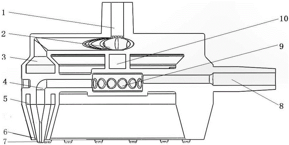
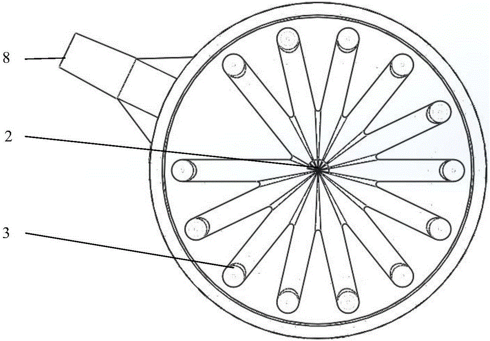
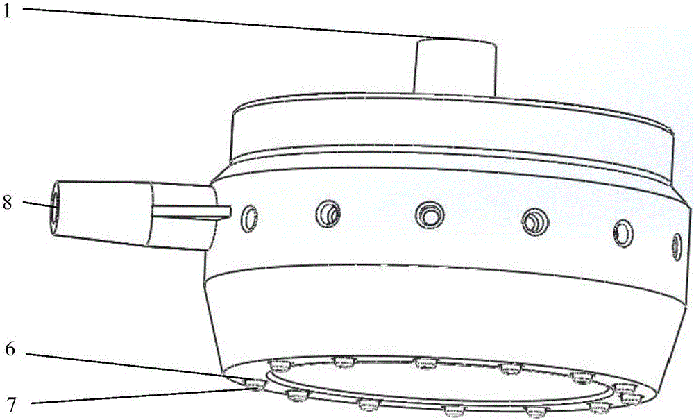
[0028] A mass production technology of multi-nozzle modules based on 3D printing technology, comprising the following steps:

[0029] Step (1): using computer-aided three-dimensional drawing software to design a single two-phase flow nozzle structure;

[0030] Step (2): Draw a module to integrate multiple nozzles at the same time;

[0031] Step (3): Using 3D printing pre-processing software to slice the three-dimensional multi-nozzle structure module layer by layer;

[0032] Step (4): Utilize the 3D printer to print out the nozzle entity;

[0033] Step (5): connect nozzles, flowmeters, constant pressure pumps, metering pumps, etc. through pipelines to form a batch particle production system.

[0034] Preferably, said 3D printer is a stereolithography (SLA) printer.

[0035] Preferably, the material of the multi-micropipe two-phase flow nozzle module is opaque resin such as pic100.

[0036] Preferably, in step (1), the single two-phase flow nozzle nozzle has a double-layer ...


PUM


Abstract

The invention discloses a technical method for large-scale production of particles by a multi-nozzle module based on a 3D (three-dimensional) printing technique and application of the technical method. The technical method is characterized in that a single nozzle is of a coaxial annular gap air blowing structure, the middle part is provided with a fluid channel, and the coaxial annular gap is an air channel; on the basis of a two-phase flow cutting principle, liquid-phase liquid is cut by air, and liquid droplet particles are produced; by controlling air and liquid outlet pressures and flow rates, the liquid droplets with different particle sizes can be obtained; the number of nozzles can be designed according to the requirement of droplet output, and liquid and air are uniformly distributed by a distributor, so as to obtain higher droplet production efficiency. The technical method has the advantages that the preparation of 3D printing nozzle modules is simple, the material cost is low, and other complicated mechanical processing methods are not required; the prepared particles are free from the pollution by poisonous matters, such as a continuous phase and surfactants; the technical method is especially suitable for preparing high-viscosity solution and suspension droplets containing insoluble particles, is widely applied to the fields of medical care, petroleum, biology, environment protection and the like, and is suitable for large-scale industrial production.

Description

technical field [0001] The invention relates to the technical field of preparing microparticles by a microfluidic chip, in particular to a multi-nozzle module based on 3D printing and its mass particle production technology. Background technique [0002] Functional microparticle materials have important applications in many fields such as bioengineering, catalytic reaction, chemical adsorption and pharmaceutical fields. Ideal spherical particles require a relatively uniform particle size distribution, stable chemical properties, and little harm to the environment and biology. The particle preparation process requires simple and fast, easy to control particle size, low cost, and easy to scale up mass production. However, in traditional preparation methods, such as film dispersion, mechanical stirring, static mixing, colloid mill and ultrasonic dispersion, etc., although large-scale production can be effectively carried out, generally only spherical particles can be obtained, ...

Claims


Application Information

Patent Timeline
IPC IPC(8): B01L3/00B29C64/10B33Y10/00
CPCB01L3/502761B01L2400/02B01L2400/0463B33Y10/00
Inventor 张莉叶骠黄逸超韩腾腾王攀峰储华龙
Owner EAST CHINA UNIV OF SCI & TECH
Learn More