Bimetallic composite plate welding method

A welding method and composite plate technology, applied in welding equipment, laser welding equipment, metal processing equipment, etc., can solve the problems of low welding seam welding efficiency, increased cladding deposition amount, complicated process, etc., and achieve the improvement of cladding The effect of welding efficiency, reduction of cladding deposition amount, and simple groove form

Active Publication Date: 2017-05-10
BC P INC CHINA NAT PETROLEUM CORP +1
View PDF8 Cites 21 Cited by
  • Summary
  • Abstract
  • Description
  • Claims
  • Application Information

AI Technical Summary

Problems solved by technology

[0006] At present, the main method of domestic composite pipe production is to produce carbon steel pipe and stainless steel liner separately, and combine them by expanding or exploding. The problem of low mechanical properties
The research on the welding of metallurgical bonded bimetallic composite pipes has just started. The main welding method in the early stage is TIG (MAG), the groove type is V-shaped, and the welding sequence is to weld the cladding layer first, and then weld the base layer. The existing problem is that many welding passes lead to Low production efficiency and base welding heat input lead to poor corrosion resistance of the clad layer, and V-shaped groove surfacing welding is difficult to realize automatic production; the main welding method in the later stage is SAW+TIG (MAG), the groove type is X-type, and the welding sequence is The base layer is welded first, and then the cladding layer is welded. Although this welding method solves the problems of poor welding efficiency of the base layer and poor corrosion resistance of the cladding layer, the excessive width of the SAW weld leads to an increase in cladding layer deposition, resulting in a The use of secondary and stainless steel welding wire increases, the overall welding efficiency of the weld is still not high, and the production cost is also difficult to control

Method used


Image

  • Bimetallic composite plate welding method
  • Bimetallic composite plate welding method
  • Bimetallic composite plate welding method

Examples


Embodiment 1

[0026] In this embodiment, the (15+3)mm UNS N08825 / L450MS hot-rolled nickel-based composite plate is taken as an example for welding, and the size of the welded test plate is 200×600mm.

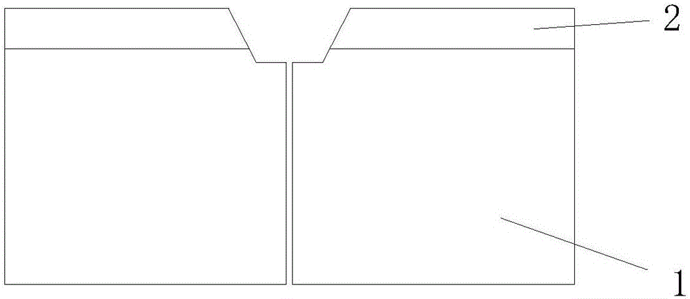
[0027] Step 1: Make I-type and V-type grooves on the welding test plate, such as figure 1 As shown, the specific dimensions are: the thickness of the base layer 1 is 15mm, the thickness of the compound layer 2 is 3mm, the height of the I-shaped groove is 14mm, the angle of the V-shaped groove is 60°, and the width of the bottom of the V-shaped groove is 4mm.

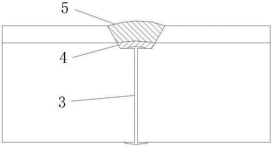
[0028] Step 2: Butt the welding test plates, and use laser welding to weld the I-shaped groove without filler wire. The distance between the two plates is not greater than 0.5mm, and the specific welding parameters are shown in Table 1. Use an angle grinder to clean the base weld 3 stainless steel side to create good welding conditions for transitional layer welding.

[0029] Step 3: TIG is used to perform welding on the base welding ...

Embodiment 2

[0040] In this embodiment, the (6+2)mm 2205 / L450MS explosion+rolled composite plate is taken as an example for welding, and the size of the welding test plate is 200×600mm.

[0041] Step 1: Make I-type and V-type grooves on the welding test plate, such as figure 1 As shown, the specific dimensions are: the thickness of the base layer 1 is 6mm, the thickness of the compound layer 2 is 2mm, the height of the I-shaped groove is 5mm, the angle of the V-shaped groove is 60°, and the width of the bottom of the V-shaped groove is 4mm.

[0042] Step 2: Butt the welding test plates, and use plasma welding to weld the I-shaped groove without filling wire. The distance between the two plates shall not be greater than 0.5mm. Use an angle grinder to clean the base weld 3 stainless steel side to create good welding conditions for transitional layer welding.

[0043] Other steps are the same as in Example 1.

[0044] The welding parameters of the base layer are shown in Table 4, and the w...


PUM

PropertyMeasurementUnit
thicknessaaaaaaaaaa
thicknessaaaaaaaaaa
thicknessaaaaaaaaaa

Abstract

The invention discloses a bimetallic composite plate welding method. The method comprises the steps that grooves are machined, after bimetallic composite plates are connected in a butt joint manner, I-type grooves are machined in base layers, V-type grooves are machined in composite layers, the height of the I-type grooves is 0.5-2 mm lower than the thickness of the base layers, the angle of the V-type grooves ranges from 50 degrees to 70 degrees, and the width of the bottoms of the V-type grooves ranges from 3 mm to 8mm; base layer welding, transition layer welding and composite layer welding are conducted sequentially, and the weld bead height of the composite layers is not lower than that of the composite layer. By the adoption of the bimetallic composite plate welding method, the groove manner is simple, one-time efficient welding of base layer weld beads can be achieved, the welding cladding amount of the composite layers is reduced by reducing the width of the base layer weld beads, and thus the purposes that welding wires are saved, and the welding efficiency of the composite layers is improved are achieved.

Description

[0001] Technical field: [0002] The invention relates to the technical field of layered structure bimetal welding, in particular to a welding method for a bimetal composite plate. [0003] Background technique: [0004] For high H 2 S / CO 2 In the exploitation of highly corrosive oil and gas fields and oil and gas transportation, the traditional single anti-corrosion technology, such as adding corrosion inhibitors, using plastic inner coatings and using non-metallic pipes, etc., has been difficult to meet the needs in terms of corrosion resistance reliability and economic indicators. Although the use of corrosion-resistant alloy pipes can greatly improve the corrosion resistance of pipes, its high price and lower strength than carbon steel seriously restrict its application in oil and gas fields, and corrosion-resistant alloy pipes are only used as corrosion-resistant parts. There is only about one-third of the overall pipe, and the remaining part is used as a mechanical supp...

Claims


Application Information

Patent Timeline
Patent Type & Authority Applications(China)
IPC IPC(8): B23K28/02B23K26/21B23K10/02B23K9/167B23K9/173
CPCB23K9/167B23K9/173B23K10/02B23K26/21B23K28/02
Inventor 田磊毕宗岳刘海璋牛辉杨军杨耀斌张万鹏黄晓辉陈长青刘刚伟牛爱军席敏敏赵红波刘斌包志刚
Owner BC P INC CHINA NAT PETROLEUM CORP
Why Eureka
Try Eureka