Plastic plate periphery polishing machine

A technology of polishing machine and plastic plate, applied in the field of polishing machine, can solve the problems of increased cost, inability to chamfer the corners of the plastic plate, inability to slot the plastic plate, etc., and achieve the effects of cost reduction, convenient and accurate position adjustment, and reduction of processes.

Inactive Publication Date: 2017-05-10
佛山市顺德区新大陆机械制造有限公司
View PDF6 Cites 0 Cited by
  • Summary
  • Abstract
  • Description
  • Claims
  • Application Information

AI Technical Summary

Problems solved by technology

[0002] The existing polishing machine around the plastic plate can automatically polish the periphery of the plastic plate. It includes a machine tool, a sliding table, a pressing device and a polishing device. The sliding table is located above the machine tool and can move along the machine tool. The pressing device is located on the sliding table. There are polishing devices respectively, which can only polish the periphery of the plastic plate, and cannot chamfer the corners of the plastic plate, nor can it groove the plastic plate. It can only be chamfered and grooved through other processes, resulting in cost increase

Method used


Image

  • Plastic plate periphery polishing machine
  • Plastic plate periphery polishing machine
  • Plastic plate periphery polishing machine

Examples


Embodiment 1

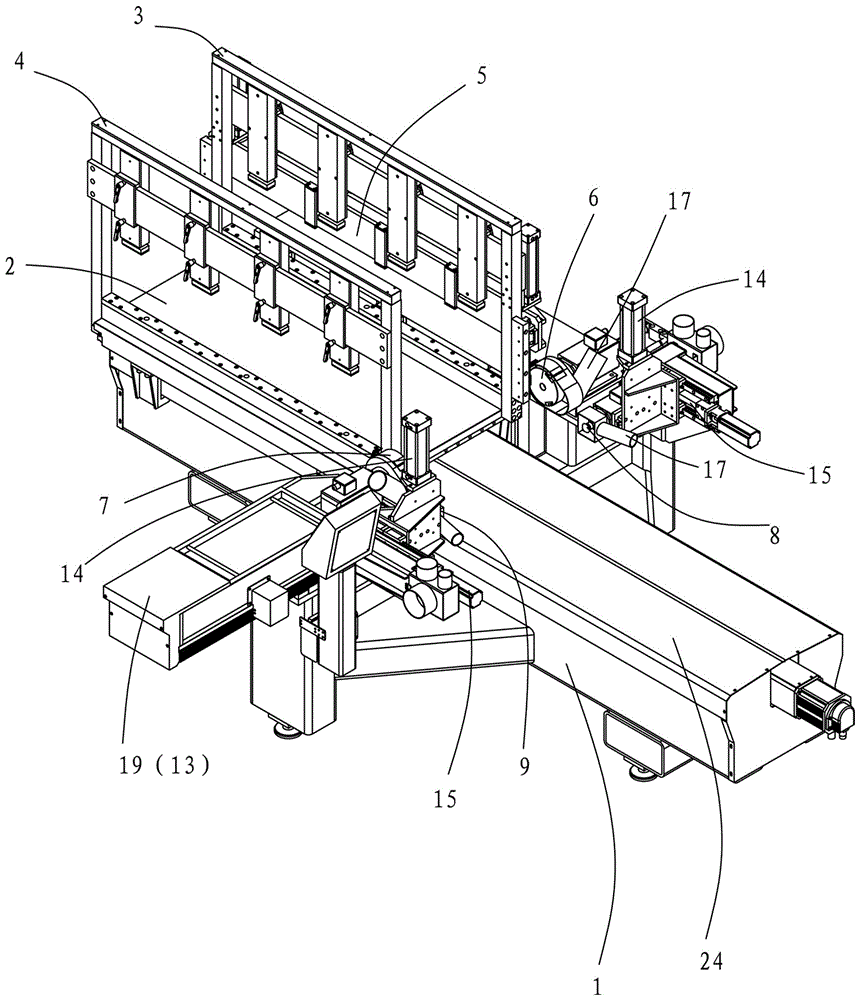
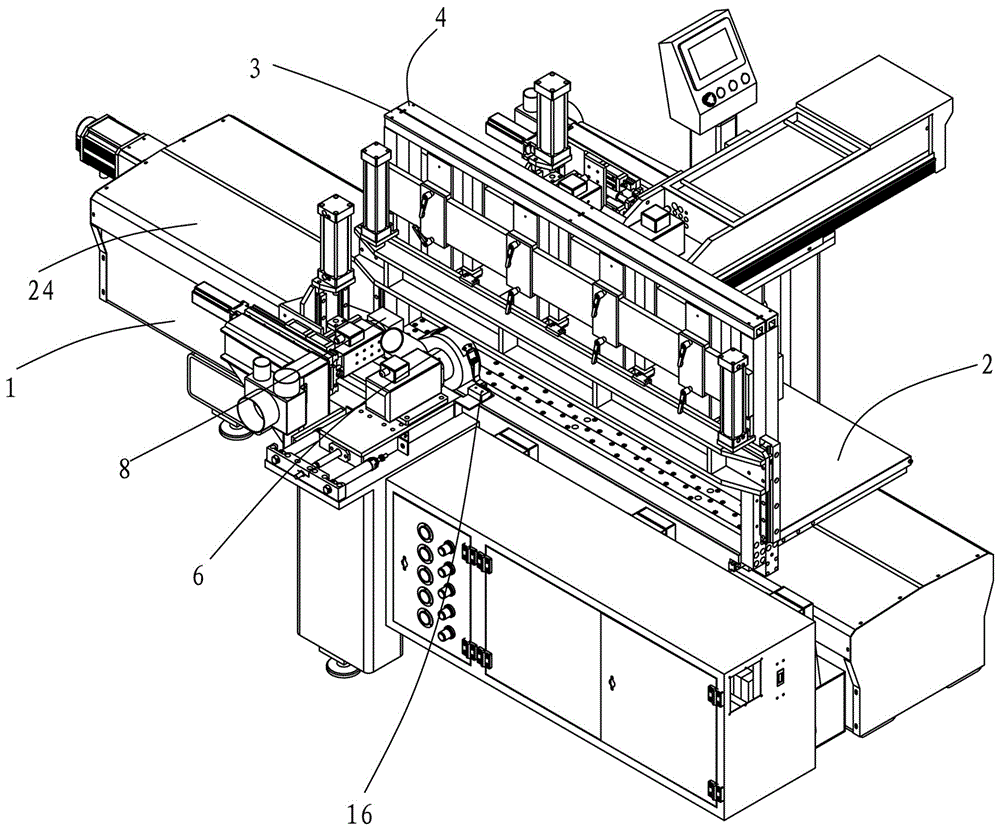
[0025] Embodiment 1, combining Figure 1 to Figure 7 , a peripheral polishing machine for plastic plates, comprising a machine tool 1, a slide table 2, a pressing device, a polishing device and a chamfering device.

[0026] The pressing device is arranged on the sliding table 2, and the pressing device includes a set of positioning pressing row 3 fixed on the sliding table and a set of dynamic pressing row 4 that can move relative to the positioning pressing row 3, and the dynamic pressing row 4 Can be close to or away from the positioning binder row 3 by manual or electric adjustment, the positioning binder row 3 is provided with a positioning plate 5, and the positioning plate 5 can move up and down relative to the surface of the slide table 2 through the cylinder drive. The main function of the positioning plate 5 is to locate the initial position of the plastic plate, and calculate the distance between the positioning binder row and the dynamic binder row according to the ...

Embodiment 2

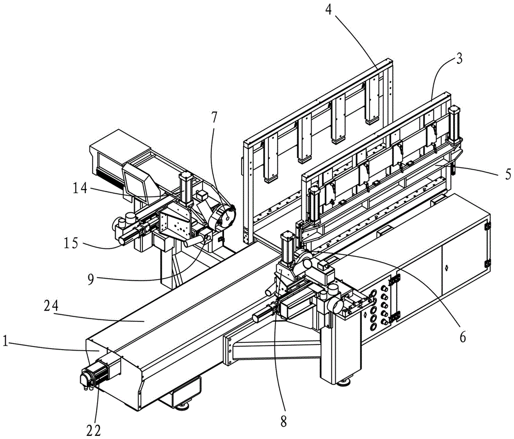
[0032] Example 2, combined with Figure 8 and Figure 9 , Embodiment 2 is mainly to carry out slotting to the periphery of plastic plate, therefore only need to pull down the cutter of the chamfering device of Embodiment 1, replace the cutter 32 of slotting device and get final product, cutter 32 is driven to rotate by motor 33, at this moment Two sets of chamfering devices become two sets of slotting devices 30,31. The structure and working principle of embodiment 2 are the same as embodiment 1.


PUM


Abstract

The invention relates to a polishing machine for polishing the periphery of a plastic plate. The polishing machine for polishing the periphery of the plastic plate comprises a machine tool, a sliding table, a material pressing device and polishing devices; the sliding table is located above the machine tool and can move along the machine tool; the material pressing device is arranged on the sliding table; the polishing devices are arranged on the two sides of the machine tool; the two sides of the machine tool are further each provided with a material cutting device; each material cutting device comprises a tool and a motor; the motors drive the tools to rotate; each material cutting device is provided with a position adjusting mechanism; and a position detector is further arranged on the side face of the machine tool and is in signal connection with each material cutting device. Polishing and chamfering can be performed at the same time, or polishing and grooving are performed at the same time as long as a chamfering device or a grooving device is added behind the polishing devices, the work procedures are greatly reduced, cost is greatly reduced, the automation degree is remarkably improved, chamfering of the chamfering device is fast, grooving of the grooving device is fast, and position adjustment of the material cutting devices is convenient and accurate.

Description

technical field [0001] The invention relates to a polishing machine for polishing the periphery of a plastic plate. Background technique [0002] The existing polishing machine around the plastic plate can automatically polish the periphery of the plastic plate. It includes a machine tool, a sliding table, a pressing device and a polishing device. The sliding table is located above the machine tool and can move along the machine tool. The pressing device is located on the sliding table. There are polishing devices respectively, which can only polish the periphery of the plastic plate, and cannot chamfer the corners of the plastic plate, nor can it groove the plastic plate. It can only be chamfered and grooved through other processes, resulting in Higher costs. Contents of the invention [0003] Therefore, the object of the present invention is to provide a polishing machine for the periphery of the plastic plate, which can perform chamfering or slotting on the periphery o...

Claims


Application Information

Patent Timeline
IPC IPC(8): B24B9/20B24B29/02B26D1/12B26D7/22
CPCB24B9/20B24B29/02B26D1/12B26D7/22
Inventor 何沛明
Owner 佛山市顺德区新大陆机械制造有限公司
Why Eureka
Try Eureka