Mixer truck for concrete transport

A technology of mixer truck and concrete, which is applied in the direction of concrete transportation, cement mixing device, clay preparation device, etc., to achieve the effect of increasing bonding strength and tight bonding

Inactive Publication Date: 2017-05-10
重庆健杰科技有限公司
View PDF7 Cites 9 Cited by
  • Summary
  • Abstract
  • Description
  • Claims
  • Application Information

AI Technical Summary

Problems solved by technology

[0006] The present invention aims at the technical problem that the existing mixer truck has limited improvement of the bonding strength of aggregate and cement, and provides a mixer truck for concrete transportation

Method used


Image

  • Mixer truck for concrete transport
  • Mixer truck for concrete transport

Examples


Embodiment 1

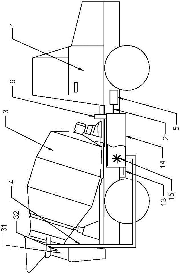
[0025] Basic as attached figure 1 Shown: a mixer truck used for concrete transportation, including a car body 1 and a mixing drum 3 . In fact, the better method of this program is to select an existing mixer truck and improve the existing mixer truck. This embodiment is to select an existing mixer truck whose emission standard has reached the national standard. If the national standard is reached, there are many impurities in the exhaust gas, which will dissolve into the water in the water tank 14, and eventually affect the quality of the concrete. The vehicle body 1 includes an exhaust pipe 12 , an air braking system 5 and a water tank 14 filled with water, and a discharge pipe 13 is arranged between the exhaust pipe 12 and the water tank 14 . What discharge pipe 13 was selected for use is a steel pipe, because the tail gas temperature discharged in the exhaust pipe 12 is still very high, if the insufficient high temperature resistant pipes such as rubber pipes and plastic p...

Embodiment 2

[0030] Compared with Embodiment 1, the only difference is that a selective catalytic reduction device is provided between the exhaust pipe 12 and the exhaust pipe 13 , and a particle trap is provided on the exhaust pipe 13 .

Embodiment 3

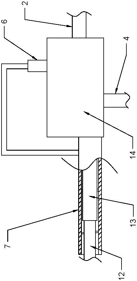
[0032] Compared with Embodiment 1, the only difference is that it also includes a cooling pipe 7, the cooling pipe 7 is sheathed on the exhaust pipe 12 and the discharge pipe 13, and supports are uniformly provided between the cooling pipe 7 and the exhaust pipe 12 and the discharge pipe 13 column, the cooling pipe 7 communicates with the outlet pipe 6, and the airflow direction between the cooling pipe 7 and the exhaust pipe 12 and the discharge pipe 13 is opposite to the airflow direction in the exhaust pipe 12 (as figure 2 shown). The high temperature of the exhaust gas will gradually heat up the water in the water tank 14. When the gas in the water tank 14 is discharged, it will carry a part of the steam. The steam will take away heat during the evaporation process, so it enters the cooling pipe 7 The temperature of the gas will be lower than the temperature in the tail gas pipe 12, and the cooling pipe 7 can initially cool the tail gas pipe 12 to prevent the temperature ...


PUM


Abstract

The invention belongs to the field of concrete transporters and particularly discloses a mixer truck for concrete transport, comprising a truck body and a stirring barrel; the truck body comprises an exhaust pipe, a pneumatic brake system and a water tank holding water, a discharge pipe is arranged between the exhaust pipe and the water tank, one end of the discharge pipe is fixedly connected to the exhaust pipe, the other end of the exhaust pipe is immersed in the water tank below the water level, the discharge pipe is provided with a one-way valve, a pressure pipe is arranged between the pneumatic brake system and the water tank and is provided with a pressure valve, the stirring barrel comprises a discharge port, the discharge port is provided with a nozzle, a water spray pipe is arranged between the nozzle and the water tank, one end of the water spray pipe is fixedly connected to the nozzle, the other end of the water spray pipe is immersed in the water tank below the water level, the water spray pipe is provided with a water spray valve, and the water tank is provided with a gas discharge pipe which is provided with a gas discharge valve. The mixer truck for concrete transport is provided to solve the technical problem that an existing mixer truck is limited to the improvement of aggregate and cement bonding strength.

Description

technical field [0001] The invention relates to the field of concrete transportation devices, in particular to a mixer truck. Background technique [0002] In the past few years, on the construction site, in order to reduce the cost, the concrete was usually mixed by the construction party itself. However, the quality of such concrete is not uniform, which increases the management cost of the construction party. With the rise of the mixing station, the concrete is now uniformly mixed by the mixing station, and then transported to the place where it is needed by the mixer truck. The mixing station usually uses automatic mixing to produce concrete, so that the quality of the concrete is relatively uniform. [0003] The mixer truck includes a car body and a mixing drum. The mixing drum is connected to the car body in rotation. There are two helical stirring blades fixed in the mixing drum. However, they are misaligned by 180°), there is a deceleration mechanism between the mi...

Claims


Application Information

Patent Timeline
Patent Type & Authority Applications(China)
IPC IPC(8): B28C5/42F01N3/04B60P3/16
CPCB28C5/4203B28C5/4244B60P3/16F01N3/04F01N2570/10F01N2590/08B28C5/4231
Inventor 黄建国
Owner 重庆健杰科技有限公司
Why Eureka
Try Eureka