
Chassis cooling system for battery pack

A chassis cooling and battery pack technology, applied in secondary batteries, battery pack components, battery/battery traction, etc. Enhanced sealing, good heat dissipation effect

Pending Publication Date: 2017-05-10
祝凤娟
View PDF0 Cites 15 Cited by
  • Summary
  • Abstract
  • Description
  • Claims
  • Application Information

AI Technical Summary

Problems solved by technology

The heat dissipation system of new energy vehicles currently adopting air-cooling mode adds fans, windshields and other devices. The heat dissipation capacity of the air-cooled heat dissipation system in the prior art is proportional to the volume, and the heat dissipation capacity of the air-cooled heat dissipation system is limited and the efficiency is low. ;It is easy to generate vibration, and it is difficult to apply to occasions with high heat dissipation pressure and limited space
[0003] At present, the new energy vehicles that use water cooling to cool the battery pack in the prior art have the following problems: 1) The layout of each component is too scattered and not compact enough, occupying some unnecessary installation space; 2) The instantaneous cooling efficiency is low, Because the battery pack generates a lot of heat at the moment of charging and discharging, the water cooling system in the prior art cannot discharge the heat in a short time, which affects the life of the battery pack and the power output of the new energy vehicle. In addition, the layout of the water cooling system is scattered, causing water to pass through Long, affecting the cooling efficiency; 3) The heat dissipation effect is not ideal
The entire cooling system finally cools down by blowing the outer surface of the water tank with a fan, which has limited heat dissipation capacity, high operating costs, high energy consumption, and complicated operation

Method used


Image

  • Chassis cooling system for battery pack
  • Chassis cooling system for battery pack

Examples


Embodiment Construction

[0024] Below in conjunction with accompanying drawing and specific embodiment the present invention is described in further detail:

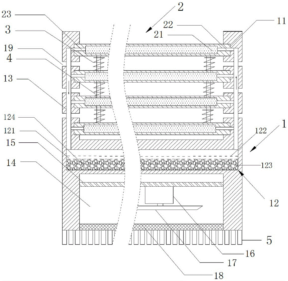
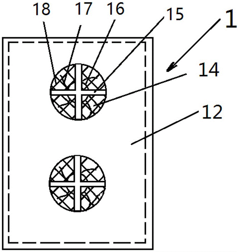
[0025] Such as figure 1 As shown, a battery pack chassis cooling system includes a chassis case 1 with an opening facing upwards and a plurality of battery pack separators 2. The inner wall of the chassis case 1 is provided with multiple slide grooves 11, and the battery pack partitions The plate 2 is inlaid inside the chute 11, and the inside of the battery pack separator 2 is provided with a liquid storage chamber 21 filled with a negative thermal expansion material, and a water inlet channel 22 and a water outlet channel 23 respectively communicating with the liquid storage chamber 21. The chassis shell 1 is provided with a cooling chamber 12 and a channel 13 communicating with the water inlet channel 22 and the water outlet channel 23 respectively. They are connected to form a cooling liquid passage, and the air bag 124 is filled in the coo...


PUM


Abstract

The invention relates to a chassis cooling system for a battery pack. The chassis cooling system comprises a chassis shell which opens upwards and a plurality of battery pack separating plates. A plurality of sliding grooves are formed in the inner side wall of the chassis shell, and the battery pack separating plates are embedded into the sliding grooves. A liquid storage cavity filled with negative thermal expansion materials is formed in each battery pack separating plate, and a water inlet channel and a water outlet channel which both communicate with the liquid storage cavity are also formed in each battery pack separating plate. A cooling cavity and ducts communicating with the water inlet channels and the water outlet channels are formed in the chassis shell, the cooling cavity communicates with the ducts communicating with the water inlet channel and the water outlet channel to form a cooling liquid passage, and the cooling cavity is filled with air bags.

Description

technical field [0001] The invention relates to the field of new energy vehicles, in particular to a battery pack chassis cooling system. Background technique [0002] At present, the cooling methods widely used in new energy vehicle battery packs mainly include air cooling and water cooling. The heat dissipation system of new energy vehicles currently adopting air-cooling mode adds fans, windshields and other devices. The heat dissipation capacity of the air-cooled heat dissipation system in the prior art is proportional to the volume, and the heat dissipation capacity of the air-cooled heat dissipation system is limited and the efficiency is low. ; It is easy to generate vibration, and it is difficult to apply to occasions with high heat dissipation pressure and limited space. [0003] At present, the new energy vehicles that use water cooling to cool the battery pack in the prior art have the following problems: 1) The layout of each component is too scattered and not co...

Claims


Application Information

Patent Timeline
IPC IPC(8): B60K1/04B60L11/18H01M2/10H01M10/613H01M10/625H01M10/6554H01M10/6556H01M10/6563H01M10/6568
CPCH01M10/613H01M10/625H01M10/6554H01M10/6556H01M10/6563H01M10/6568B60K1/04B60L50/66B60L58/26H01M50/20Y02T90/16Y02T10/70Y02E60/10
Inventor 祝凤娟
Owner 祝凤娟
Learn More