Hybrid Electric Vehicle, Motor Drive Transmission System and Its Vibration Damping Mechanism

A vibration damping mechanism and motor-driven technology, which is applied to the arrangement of multiple prime movers of the power unit, the general power unit, and the air pressure power unit, etc., can solve problems such as reducing the service life of the product, damaging the transmission, and harming the human ear. , to prolong the service life, reduce noise and avoid harm

Active Publication Date: 2019-07-19
SAIC MOTOR
View PDF5 Cites 0 Cited by
  • Summary
  • Abstract
  • Description
  • Claims
  • Application Information

AI Technical Summary

Problems solved by technology

[0006] The problem solved by the present invention is that in a hybrid vehicle, the motor drive transmission system will generate high-frequency vibrations and cause resonance problems. This resonance will not only generate relatively large noises, which will cause harm to human ears, but will also damage parts such as transmissions, reducing Product life

Method used


Image

  • Hybrid Electric Vehicle, Motor Drive Transmission System and Its Vibration Damping Mechanism
  • Hybrid Electric Vehicle, Motor Drive Transmission System and Its Vibration Damping Mechanism
  • Hybrid Electric Vehicle, Motor Drive Transmission System and Its Vibration Damping Mechanism

Examples


no. 1 example

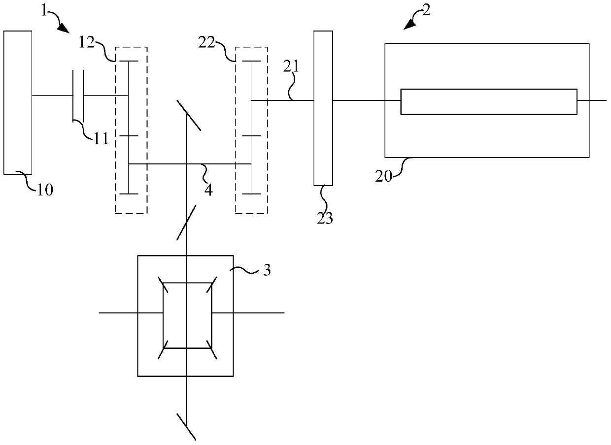
[0051] refer to figure 1 , the hybrid vehicle has two sets of power systems, which are the engine transmission system 1 and the motor drive transmission system 2 respectively. The motor drive transmission system 2 includes:

[0052] An electric motor 20, the electric motor 20 has a rotor and a stator (not shown in the figure), and both the rotor and the stator have several windings;

[0053] The intermediate shaft 21, the torque generated by the rotation of the rotor 2 is output to the final drive (not shown in the figure) and the differential 3 through the intermediate shaft 21 and the gear transmission mechanism 22 on the intermediate shaft 21;

[0054] The damping mechanism 23 is located between the intermediate shaft 21 and the rotor and is fixedly connected to the intermediate shaft 21 and the rotor respectively.

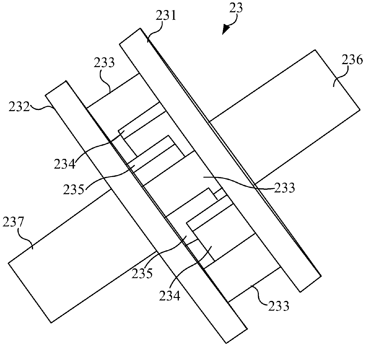
[0055] combined reference figure 2 , the damping mechanism 23 of this embodiment includes: a first support part 231, the first support part 231 is fixedly ...

no. 2 example

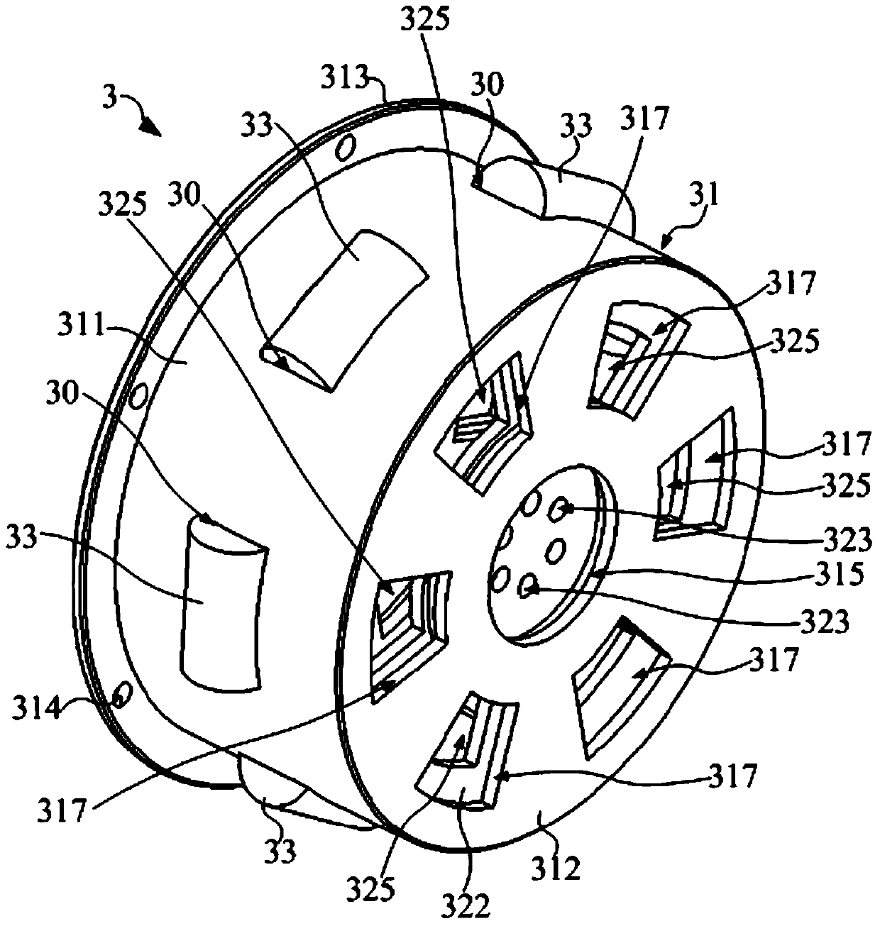
[0073] Unlike the first embodiment, refer to Figure 3 ~ Figure 5 , this embodiment is used in the damping mechanism 3 of the motor-driven transmission system, the first support part 31 includes a first ring part 311 and the second support part 32 includes a second ring part 321, and the first and second ring parts are the same The shaft is arranged on both sides along the axial direction of the first and second annular parts 311 and 321, one axial end of the first annular part 311 on one side is used to connect the intermediate shaft, and the second support part 32 on the other side is used for connecting the rotor;

[0074] The shock absorber 33 is connected between the first and second ring parts 311 and 321 and is used for extrusion deformation when the first support part 31 and the second support part 32 rotate relative to each other.

[0075] The first support part 31 can rotate around its own central axis relative to the second support part 32, and the shock absorber 3...


PUM


Abstract

The invention provides a hybrid electric vehicle, a motor driving transmission system and a vibration reduction mechanism of the system. A motor driving transmission mechanism comprises a middle shaft, a rotor, a first supporting part, a second supporting part and a vibration reduction element. The first supporting part is used for being connected with the middle shaft, and the second supporting element is used for being connected with the rotor; the vibration reduction element is connected between the first supporting part and the second supporting part and made of a damping material. In the motor driving transmission system, the first supporting part in the vibration reduction mechanism is connected with the rotor of a motor, and the second supporting part is fixedly connected with the middle shaft of the motor driving transmission system. By means of the vibration reduction mechanism, the vibration reduction element can well attenuate high-frequency vibration of the motor driving transmission system, the frequency of the high-frequency vibration is attenuated below the normal rotation speed of the motor, the resonance problem caused by high-frequency vibration is effectively reduced, noise generated by resonance can be reduced, human ears are prevented from being harmed, the situation that the motor, a transmission and other parts are damaged due to resonance is also avoided, and the service life of products is prolonged.

Description

technical field [0001] The invention relates to the technical field of hybrid electric vehicles, in particular to a hybrid electric vehicle, a motor-driven transmission system and a damping mechanism thereof. Background technique [0002] Existing hybrid vehicles include an engine power transmission system and a motor drive transmission system. In the engine power transmission system, the torque of the engine can be transmitted to the transmission input shaft of the transmission system through the clutch, and output through the transmission output shaft. In the motor-driven transmission system, the rotor of the motor rotates to generate torque, which is output through an intermediate shaft. Finally, the torque generated by the two sets of transmission systems is transmitted to the final drive and differential through their respective gear transmission mechanisms. [0003] In the engine power transmission system, in order to avoid the resonance problem caused by the vibrati...

Claims


Application Information

Patent Timeline
Patent Type & Authority Patents(China)
IPC IPC(8): B60K6/26B60K6/40H02K7/00
Inventor 徐旭初朱新星葛凤龙陶林杰张伯平赵朝阳
Owner SAIC MOTOR
Why Eureka
Try Eureka