The superstructure of the prefabricated uncapped beam-type composite steel plate girder bridge and its assembling construction method
A steel plate and cover girder technology, applied in bridges, bridge parts, bridge construction, etc., can solve the problems of bad urban landscape effects, heavy weight of small box girders and T girders, and high requirements for construction equipment, so as to optimize bridge landscape and reduce Complexity and on-site operation difficulty, effect of reducing hoisting weight
- Summary
- Abstract
- Description
- Claims
- Application Information
AI Technical Summary
Problems solved by technology
Method used
Image
Examples
Embodiment 1
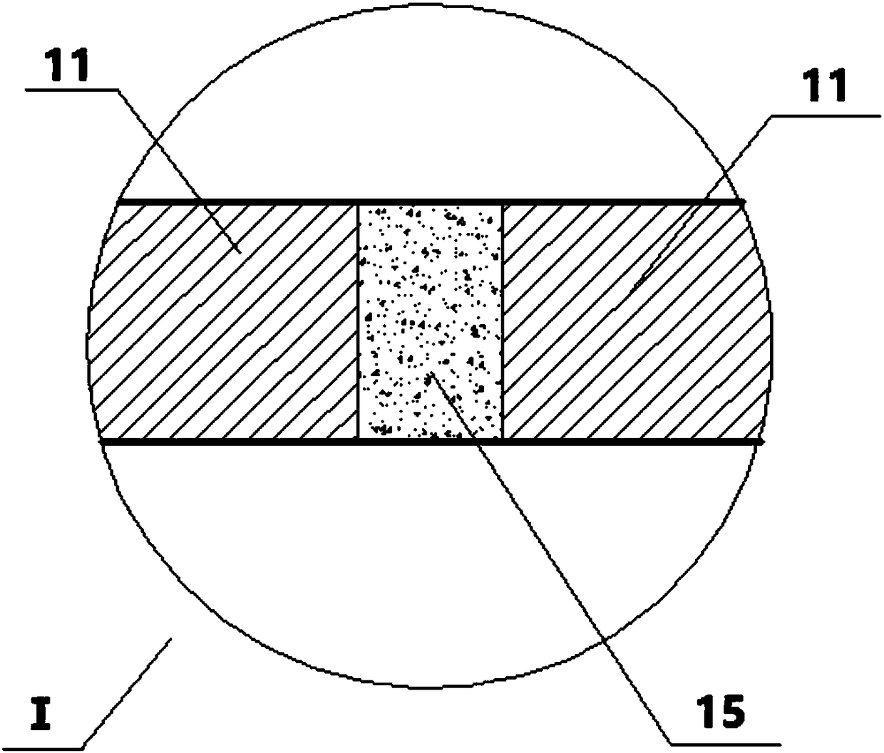
[0041] Such as Figure 6 As shown, the superstructure 7 of the prefabricated uncapped girder type composite steel plate girder bridge of the present invention includes multiple composite steel plate longitudinal girders 1 and fulcrum concrete beams 2, and the multiple composite steel plate longitudinal girders 1 are combined to form the bridge main girder along the horizontal direction of the bridge. The two ends of the main girder of the bridge are respectively provided with a fulcrum concrete beam 2 . Such as Figure 4 As shown, the fulcrum concrete beams 2 at both ends of the main girder of each span bridge are supported on the support 3 at the top of the pier column of the lower structure of the bridge.
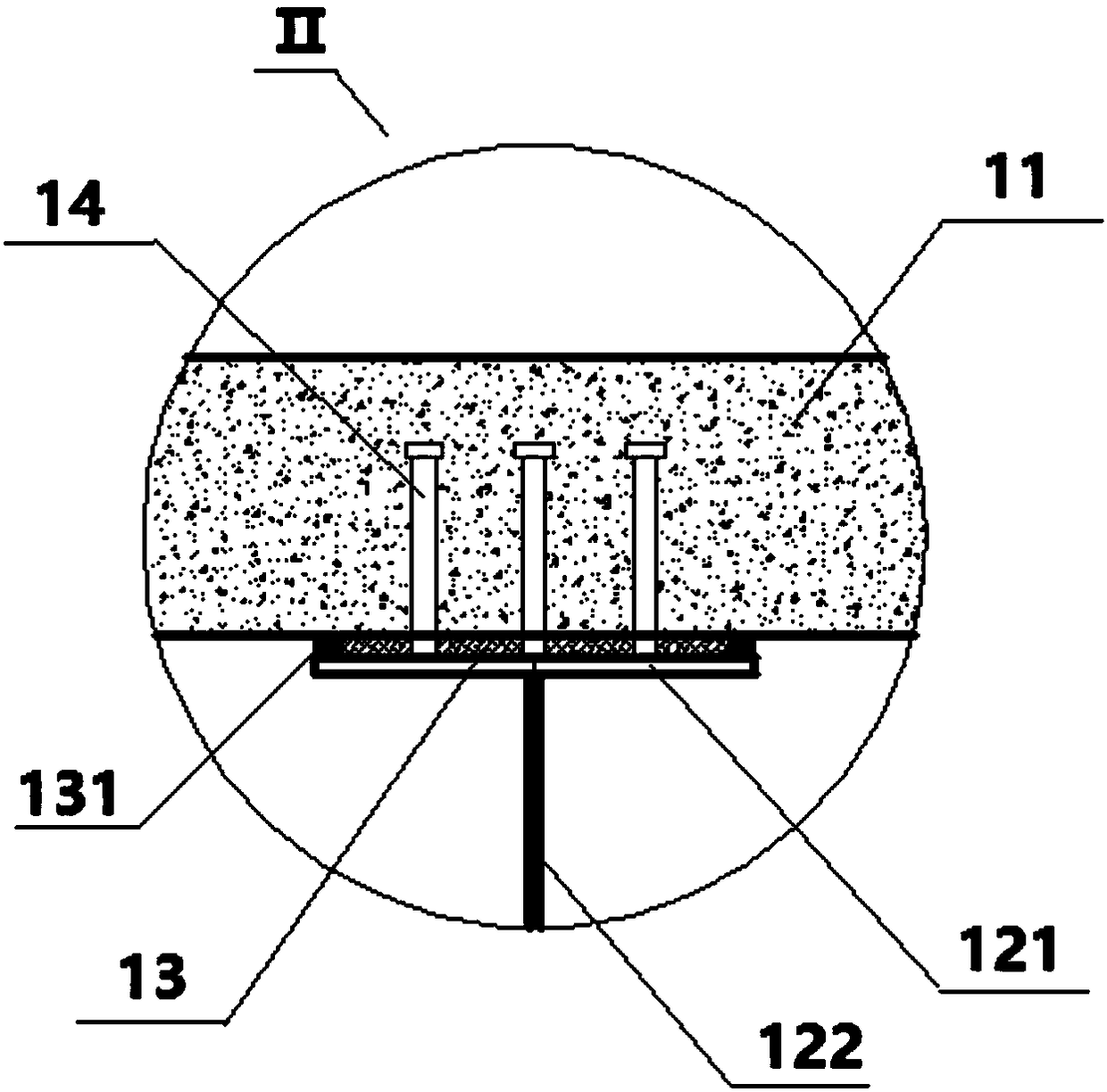
[0042] Such as figure 1 , 4 As shown, each composite steel plate longitudinal girder 1 includes a prefabricated concrete bridge deck 11 and an I-shaped steel girder 12, and the I-shaped steel girder 12 includes a top plate 121, a bottom plate 123 and a web 122, and the...
Embodiment 2
[0051] The assembling construction method of embodiment 1 product
[0052] Include the following steps:
[0053] A. The central combined steel plate longitudinal beam and cross beam section combination, the middle combined steel plate longitudinal beam and cross beam section combination and the side combined steel plate longitudinal beam and cross beam section combination are respectively hoisted and positioned on the completed bridge substructure, specifically The hoisting positioning sequence is as follows: Figure 8 As shown: firstly, a steel spacer 61 is set on the tie beam 6 of the lower structure of the bridge, and the joint body of the central composite steel plate longitudinal beam beam section is hoisted above the central position of the tie beam, and the central beam section at both ends of the central composite steel plate longitudinal beam The segments are respectively positioned and fixed on the steel pads at the central positions of the two tie beams, and epoxy ...
PUM
 Abstract
Description
Claims
Application Information
 - R&D
- Intellectual Property
- Life Sciences
- Materials
- Tech Scout
- Unparalleled Data Quality
- Higher Quality Content
- 60% Fewer Hallucinations
Browse by: Latest US Patents, China's latest patents, Technical Efficacy Thesaurus, Application Domain, Technology Topic, Popular Technical Reports.
© 2025 PatSnap. All rights reserved.Legal|Privacy policy|Modern Slavery Act Transparency Statement|Sitemap|About US| Contact US: help@patsnap.com


