
Shallow-buried tunnel section construction method

A construction method and technology for shallow buried tunnels, applied in tunnels, earthwork drilling, infrastructure engineering, etc., can solve the problem that shield tunneling method cannot be fully utilized for rapid construction, shield machine is frequently turned around and disassembled, and is not suitable for shield tunneling method construction and other issues, to reduce construction safety risks, reduce construction technical difficulty, and achieve the effect of construction safety

Active Publication Date: 2017-05-10
GUANGZHOU HENGSHENG CONSTR ENG
View PDF4 Cites 6 Cited by
  • Summary
  • Abstract
  • Description
  • Claims
  • Application Information

AI Technical Summary

Problems solved by technology

However, the shield method has disadvantages such as incompatibility with stratum changes and fixed sections.
Especially in the construction of the subway project, the interval tunnel built by the shield method and the station construction have contradictions in the construction period and organization, and the shield machine is frequently turned around and disassembled, etc., and the advantages of the rapid construction of the shield method cannot be fully utilized.
[0006] Especially when building a short-distance shallow tunnel across the river, the buried depth is relatively shallow and the tunnel is not long, so it is not suitable for shield construction
In addition, it is not suitable to use the underground excavation method for construction under the water, because it is afraid of water penetration, which is very dangerous
Moreover, in order to ensure navigation, only segmental construction can be adopted.

Method used


Image

  • Shallow-buried tunnel section construction method
  • Shallow-buried tunnel section construction method
  • Shallow-buried tunnel section construction method

Examples


Embodiment

[0046] 1. Introduction to the implementation project

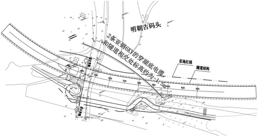
[0047] The embodiment of the present invention is located at Gangqian Road (South Petrochemical Road-Kaikai Avenue). The Nanhai Temple section of the Gangqian Road project passes near Miaotou Village. The south side of the line is Huangpu Power Plant, and the north is the famous Nanhai Temple. The Nanhai Temple was originally a temple on the coast of the South China Sea to worship the God of the South China Sea. Over time, the sedimentation carried by the Pearl River has caused the coastline to move southward, and the temple has a certain distance from the coastline. The current situation is that the bay near the temple has degenerated into a lake (belonging to the Pearl River system). The lake is about 400 meters long and 200 meters wide. The total area of ​​the lake is about 80,000 square meters. The South China Sea Temple is located on a peninsula jutting into the lake. Pineapple Lake is connected to the vast South Ch...


PUM


Abstract

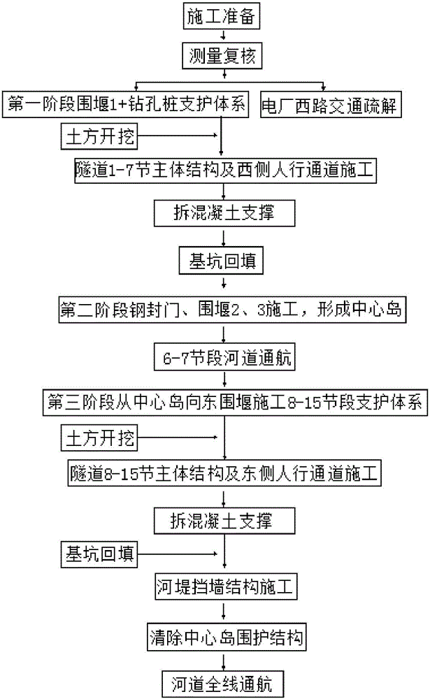
A shallow-buried tunnel section construction method comprises the following steps that tunnel front half section construction is carried out, wherein a supporting structure and a waterproof curtain are constructed from one side of a riverway to the center of the riverway to form a first cofferdam; tunnel center island construction is carried out, wherein a steel seal door and an inserted and hit steel plate pile are mounted at the position, on the inner side face of the riverway, of the first cofferdam, then the two sides of the position, of the inner side face of the riverway, of the first cofferdam are finished to form island heads, and a center island is formed; tunnel rear half section construction is carried out, wherein the center island and the other side of the riverway are utilized for constructing a supporting structure and a waterproof curtain to form a second cofferdam, tunnel rear half section construction is carried out after water drawing is carried out, and after construction is completed, full-line navigation opening up is restored. The shallow-buried tunnel section construction method has the advantages of being feasible in technology, economical, reasonable, simple in process, easy and convenient to operate and safe in construction and meets the development direction of the modern engineering technology, and therefore wide popularization prospects are achieved.

Description

technical field [0001] The invention relates to the technical field of building construction, in particular to a segmented construction method for a shallow buried tunnel. Background technique [0002] At present, the main methods for the construction of underground tunnel structures in domestic cities are open-cut method, shallow-buried underground method and shield method, but these three methods are restricted by the surrounding environment to varying degrees in the actual use process. [0003] (1) Open cut method In the case of the construction of underground space structures under the conditions of heavy traffic on the ground in the city, many surrounding buildings and many underground pipelines, traffic must be dredged or even interrupted, and pipelines must be relocated when necessary. In addition, during the construction process of open cut method, the demolition workload of ground structures is heavy, and the noise and vibration generated will also seriously interfe...

Claims


Application Information

Patent Timeline
IPC IPC(8): E21D9/00E02D19/04
CPCE02D19/04E21D9/00
Inventor 李慧莹雷达王辉张海钊陈卫文汤健维
Owner GUANGZHOU HENGSHENG CONSTR ENG
Learn More