Layer-by-layer grouting construction method for fixed-point deep hole on the surface

A construction method and grouting technology, which are used in earth-moving drilling, underground chambers, shaft equipment, etc., can solve problems such as difficult grouting in deep holes, difficulty in adapting to the surrounding rock characteristics of different fault fracture zones, and difficulty in bearing bearing pressure. Achieve the effect of avoiding frequent damage, avoiding difficulty in pulling out, and improving stress capacity

Active Publication Date: 2021-10-26
北京瑞威世纪铁道工程有限公司
View PDF7 Cites 0 Cited by
  • Summary
  • Abstract
  • Description
  • Claims
  • Application Information

AI Technical Summary

Problems solved by technology

But this invention still has the following disadvantages or deficiencies: (1), this method is not suitable for the reinforcement of shallow buried sections of tunnels crossing fault fracture zones; (2), this method uses constant grouting pressure for grouting, which is difficult to adapt to Surrounding rock characteristics of different fault fracture zones; (3) The material of the sleeve valve is polyvinyl chloride (PVC), which is difficult to withstand large load-bearing pressure, and the maximum depth can only reach about 30-40 meters, which is difficult to be used in deep holes Grouting

Method used


Image

  • Layer-by-layer grouting construction method for fixed-point deep hole on the surface
  • Layer-by-layer grouting construction method for fixed-point deep hole on the surface
  • Layer-by-layer grouting construction method for fixed-point deep hole on the surface

Examples


Embodiment Construction

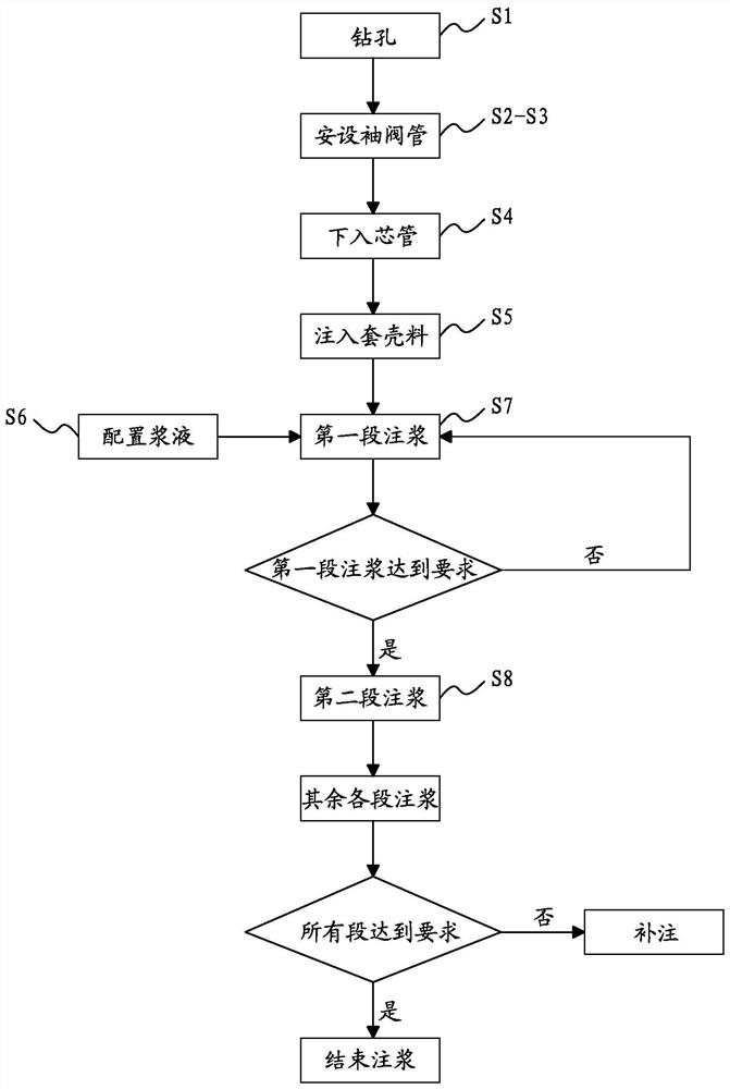
[0044] Please refer to figure 1 , 2 According to a non-limiting embodiment of the present invention, a surface fixed-point deep hole layered grouting construction method is provided, and the method includes the following steps S1-S8.

[0045] In step S1, locate the area that needs grouting and drill vertically from the construction side to the inside of the area that needs grouting. After the drilling rig completes the drilling, withdraw the drill pipe. The hole diameter is set to about 200 mm, and the hole depth is set to about 120 meters. .

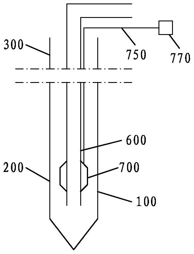
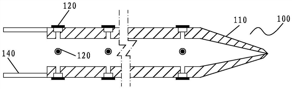
[0046] In step S2 , the type I cuff tube 100 , several type II cuff tubes 200 and several type III cuff tubes 300 are provided.

[0047] In step S3, the Type I sleeve valve tube 100 is lowered into the end of the borehole by its own weight, the Type II sleeve valve tube 200 is sequentially lowered into the designed grouting section of the borehole by its own weight, and the Type III sleeve valve tube 200 is sequentially lowered by its...


PUM


Abstract

The invention discloses a fixed-point deep hole layered grouting construction method on the surface, which comprises: vertically drilling a hole from the surface of the construction area to the interior of the area requiring grouting, and the hole depth is set at 80-150 meters. After the hole reaches the designed depth, run the Type I sleeve valve pipe (100) into the end of the borehole, and then connect the Type II sleeve valve pipe (200) section by section to the designed grouting section of the borehole, and then section by section Connect the Type III sleeve valve pipe (300) into the non-design grouting section of the borehole. After the installation of the sleeve valve tube is completed, the shell material is injected into the gap between the outer wall of the sleeve valve tube and the inner wall of the drilled hole to seal the hole. The hole sealing is completed, and after being consolidated, the grouting core pipe (600) is lowered. The end of the first grouting core pipe (600) is connected through the grout stopper (700) and the grout stopper (700), and then the rest of the grouting core pipes (600) are connected one by one and lowered into the sleeve valve pipe until A stopper (700) is lowered into the bottom of the sleeve valve tube. Connect the grouting pipeline to the end of the core pipe, prepare the grouting liquid, and start the grouting operation through the grouting core pipe (600).

Description

technical field [0001] The invention relates to the technical field of rock and soil engineering, in particular to a construction method for strengthening rock and soil. Background technique [0002] With the increasing scale of railway construction, there are more and more high-speed railway tunnels. During the tunnel construction process, the surrounding rock undergoes large deformation, the stability becomes poor, and landslide disasters occur frequently. When the tunnel construction reaches the fault fracture zone, due to the sudden drop in the grade of surrounding rock and the fact that the fault fracture zone is often rich in groundwater, the original initial support design is difficult to maintain the stability of the surrounding rock, and large-scale landslides occur. In addition, the shallow buried section of the tunnel has a thin covering layer and poor stability of the surrounding rock, and engineering accidents such as landslides are prone to occur during excava...

Claims


Application Information

Patent Timeline
Patent Type & Authority Patents(China)
IPC IPC(8): E21D11/00
CPCE21D11/00
Inventor 彭峰
Owner 北京瑞威世纪铁道工程有限公司
Why Eureka
Try Eureka