Natural gas pipe network pressure energy power generation and refrigeration house method and device

A technology of natural gas pipeline network and pressure energy, which is applied in the direction of household refrigeration equipment, steam engine equipment, coolers, etc., can solve the problem that the application of refrigeration and cold storage has not been discussed, the utilization of cold energy is limited to one temperature, and the recycling is limited to To achieve the integration of power generation and refrigeration, realize the effective use of energy, save energy and equipment

Inactive Publication Date: 2017-05-10
SHENZHEN GAS CORP
View PDF10 Cites 8 Cited by
  • Summary
  • Abstract
  • Description
  • Claims
  • Application Information

AI Technical Summary

Problems solved by technology

The pressure energy recycling device and the cold energy recycling device of this process are skid-mounted separately, which has structural advantages such as easy installation, easy disassembly, and easy maintenance, ensuring the stable operation of the original equipment and new devices, but the utilization of cold energy is limited to a temperature
Chinese patent CN205025513U discloses a comprehensive utilization system for natural gas pipeline network pressure energy recovery. This patent realizes natural gas expansion power generation and cold energy recovery. limitation
The above-mentioned processes all describe the pressure energy recovery of natural gas pipeline network for power generation and the recovery of cold energy for ice making, but there is no relevant discussion on the application of refrigeration cold storage, especially multi-temperature cold storage

Method used


Image

  • Natural gas pipe network pressure energy power generation and refrigeration house method and device
  • Natural gas pipe network pressure energy power generation and refrigeration house method and device

Examples


Embodiment Construction

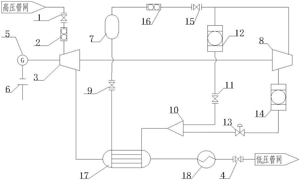
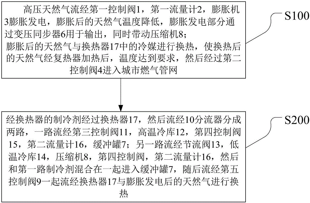
[0030] Below in conjunction with example and process flow chart (see figure 1 ) for further explanation. Such as figure 1 As shown, a natural gas pipeline network pressure energy power generation and cold storage method and device, including an expander power generation system and a refrigerant refrigeration system;

[0031] The expansion system includes a control valve 1, a flow meter 2, an expander 3, a heat exchanger 17, a reheater 18, and a control valve 4 that are sequentially connected between the high-pressure pipe network and the low-pressure pipe network through pipelines, wherein the expander 3. The rear end is also connected to the twin-shaft generator 5 and the transformer synchronizer 6; the output shaft of the turboexpander 3 is connected to one shaft of the twin-shaft generator 6, and the power of the twin-shaft generator 6 is used by site equipment Or supply power to the outside through a transformer synchronizer;

[0032] The refrigerant refrigerating syste...


PUM


Abstract

The invention discloses a natural gas pipe network pressure energy power generation and refrigeration house method and device. The device comprises an expansion power generation system and a coolant refrigeration system, wherein the expansion power generation system and the coolant refrigeration system realize power generation and refrigeration integration; the expansion power generation system is that high-pressure natural gas generates power through an expander, then exchanges heat with a coolant, and enters an urban gas pipe network; after exchanging heat with low temperature natural gas, the coolant in the coolant system passes through a distributor; and one stream is directly supplied to a high temperature refrigeration house, and the other stream is supplied to a low temperature refrigeration house after being throttled, so as to realize refrigeration house freshness retaining at different temperature levels. According to the device disclosed by the invention, the expander, a power generator and a compressor operate continuously, so that pressure energy of the pipe network is recycled for generating power and driving the compressor to rotate, externally required energy during independent use of the compressor is reduced, and cooling of two refrigeration houses at different temperature levels is realized; and the device has extremely high economical and social benefits.

Description

technical field [0001] The invention relates to a natural gas pipeline network pressure energy generation and cold storage method and device, in particular to an integrated device for pipeline network natural gas pressure energy expansion power generation and refrigerant refrigeration. Background technique [0002] Long-distance natural gas pipelines generally use high-pressure transmission. During the transmission process, it needs to be raised to high-pressure transmission through a compressor station, and needs to be depressurized at the user side. Natural gas produces a huge capacity in the process of depressurization, and the effective use of this part of energy has attracted widespread attention. [0003] The recovery of natural gas pressure energy is usually converted into mechanical energy and cold energy through an expander. Mechanical energy is often used for power generation or shaft connection, and cold energy is often used in common cold industries such as ice ...

Claims


Application Information

Patent Timeline
Patent Type & Authority Applications(China)
IPC IPC(8): F01K25/08F01K27/00F25D13/00F25B41/00F25B41/20F25B41/40
CPCF01K25/08F01K27/00F25B41/00F25D13/00
Inventor 陆涵温永刚张姝丽杜琳琳陈仲
Owner SHENZHEN GAS CORP
Why Eureka
Try Eureka