
Gas compressor plane cascade experimental system with suction baffle structure

A technology of experimental system and baffle structure, which is applied in the direction of mechanical equipment, machine/engine, liquid variable capacity machinery, etc., to achieve uniform air intake, improve internal flow, and simple operation

Active Publication Date: 2017-05-10
DALIAN MARITIME UNIVERSITY
View PDF4 Cites 21 Cited by
  • Summary
  • Abstract
  • Description
  • Claims
  • Application Information

AI Technical Summary

Problems solved by technology

The present invention mainly utilizes the cooperation of the suction device and the planar cascade experimental device. During the experiment, the cascade has better periodicity by adjusting the upper baffle and the lower baffle. The boundary layer is sucked to reduce the area affected by the boundary layer and the incoming flow is uniform, thus solving the problem of ensuring the uniformity of the airflow at the inlet of the cascade in the case of a thick boundary layer in the experiment, which has the advantages of small experiment difficulty and low cost , the advantages of simple operation

Method used


Image

  • Gas compressor plane cascade experimental system with suction baffle structure
  • Gas compressor plane cascade experimental system with suction baffle structure
  • Gas compressor plane cascade experimental system with suction baffle structure

Examples


Embodiment Construction

[0025] In order to make the purpose, technical solutions and advantages of the embodiments of the present invention clearer, the technical solutions in the embodiments of the present invention will be clearly and completely described below in conjunction with the drawings in the embodiments of the present invention. Obviously, the described embodiments It is a part of embodiments of the present invention, but not all embodiments. Based on the embodiments of the present invention, all other embodiments obtained by persons of ordinary skill in the art without making creative efforts belong to the protection scope of the present invention.

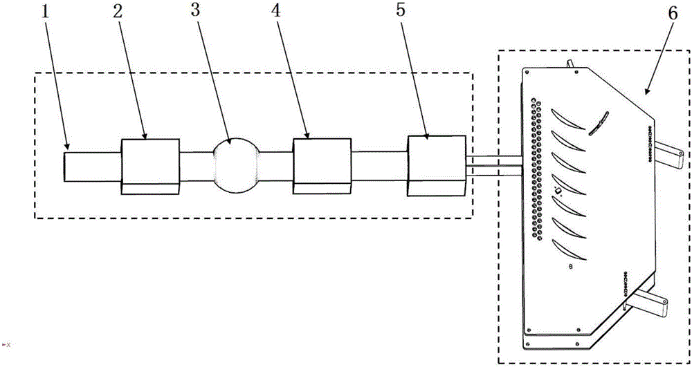
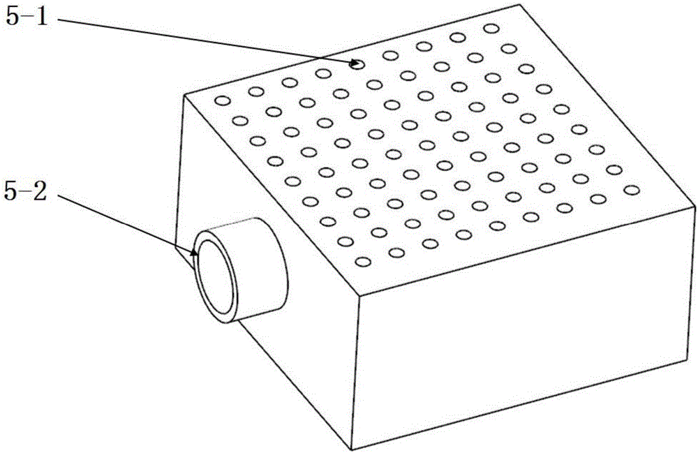
[0026] like figure 1 As shown, a compressor plane cascade experimental system with a suction baffle structure includes a suction device and a plane cascade experimental device 6; Vacuum pump air source 1, pressure stabilizing box 2, throttle valve 3, flow meter 4 and splitter box 5, water circulation vacuum pump air source 1 is used to provi...


PUM


Abstract

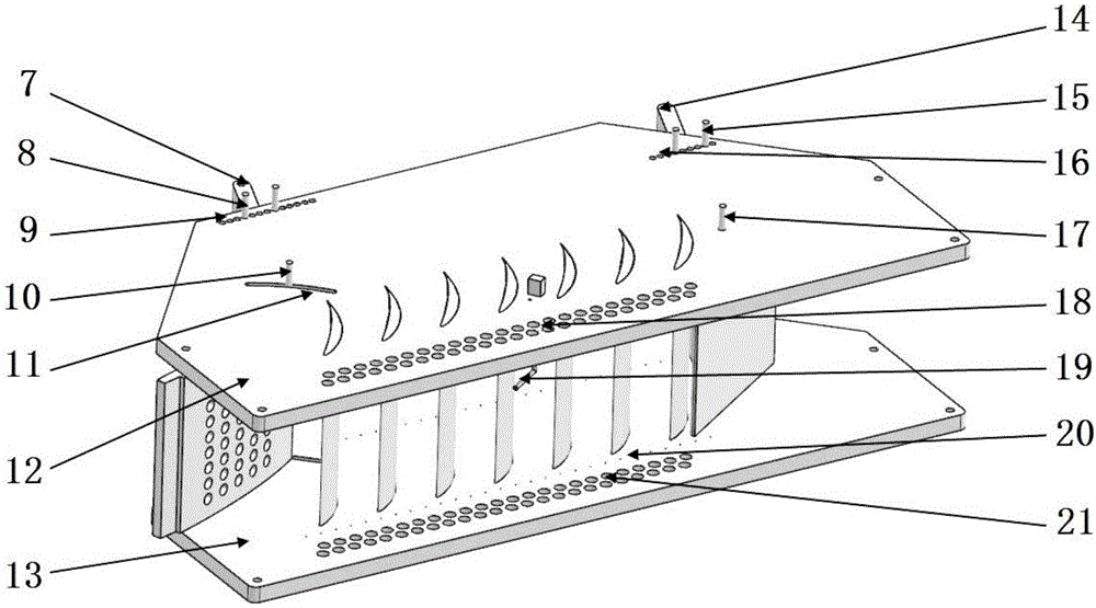
The invention provides a gas compressor plane cascade experimental system with a suction baffle structure. The gas compressor plane cascade experimental system comprises a suction device and a plane cascade experimental device. The plane cascade experimental device comprises a left end plate, a right end plate, an upper baffle, a plurality of experimental blades and a lower baffle, wherein the upper baffle is arranged between the left end plate and the right end plate, and the multiple experimental blades are distributed at intervals. The upper baffle and the lower baffle are connected between the left end plate and the right end plate through fixing shafts. The upper baffle is provided with suction holes. Left end plate suction holes are formed in the left end plate, and right end plate suction holes are formed in the right end plate. The suction holes are connected with a vacuum pump through a pipeline. A three-hole probe 1 is arranged between the left end plate and the right end plate. In the experimental process, the upper baffle and the lower baffle are adjusted so that a cascade can be good in periodicity, the boundary layer of incoming flow is sucked through the left end plate suction holes and the right end plate suction holes, the influence area of the boundary layer is reduced, and uniform incoming flow is achieved. The gas compressor plane cascade experimental system with the suction baffle structure is an effective path for exploring improvement of the performance of a gas compressor, the influence of the boundary layer of the incoming flow is reduced, and meanwhile, the periodicity of the plane cascade is improved.

Description

technical field [0001] The invention relates to a compressor plane cascade experiment system with a suction baffle structure. Background technique [0002] As an advanced power plant, gas turbines are widely used in aviation, ships, power generation, petrochemical, natural gas transmission and railway transportation due to their excellent performance. The axial flow compressor is the core component of the gas turbine. Its function is to compress the gas to a specific pressure. Its working performance under different working conditions has a direct impact on the performance of the whole machine. With the development of aviation propulsion theory, high-performance, high-thrust-to-weight ratio turbojet engines put forward higher and higher requirements on the performance of compressor blades. [0003] In the basic research on the performance of compressor blades, in addition to the theoretical research, the experimental research of the planar cascade wind tunnel occupies an ex...

Claims


Application Information

Patent Timeline
Patent Type & Authority Applications(China)
IPC IPC(8): F04B51/00F04D27/00
CPCF04B51/00F04D27/001
Inventor 孙鹏徐文峰钟兢军傅文广陆华伟
Owner DALIAN MARITIME UNIVERSITY
Learn More