Bumping position measuring system and method based on bidirectional detection of fiber ring

A measurement system and optical fiber ring technology, applied in the field of measurement, can solve the problems of inapplicability to long-distance interception and collision measurement, measurement failure, high cost, etc., and achieve the effects of large-scale promotion, simplified structure complexity, and reduced measurement cost

Inactive Publication Date: 2017-05-10
BEIJING INST OF AEROSPACE CONTROL DEVICES
View PDF6 Cites 7 Cited by
  • Summary
  • Abstract
  • Description
  • Claims
  • Application Information

AI Technical Summary

Problems solved by technology

[0003] The existing relatively advanced measurement methods in shooting ranges at home and abroad are difficult to measure the centimeter-level impact part under the condition of high-altitude and ultra-high-speed collision. For example, the optical multi-station same-frame frame frame miss measurement system has an accuracy of about 3m when observing the oblique distance of 300km , the accuracy further decreases when the slant distance is farther; the measurement accuracy of the radio stepping frequency broadband miss-target measurement system is about 0.3m without considering the body effect; In the case of body effect, the measurement accuracy is about 0.2m; due to the long response time of these methods, they are not suitable for long-distance interception collision measurement
In addition, emerging impact measurement systems, such as the electric grid target line impact point measurement system and the multi-point ultrasonic impact point measurement system, have a response time of ten milliseconds, and cannot complete centimeter-level impacts within the shortest system survival time of about ten microseconds. Part measurement tasks, and are susceptible to electromagnetic interference, which seriously affects the measurement results and even leads to measurement failures
Moreover, the existing measurement scheme still has the problems of many devices, complex structure and high cost

Method used


Image

  • Bumping position measuring system and method based on bidirectional detection of fiber ring
  • Bumping position measuring system and method based on bidirectional detection of fiber ring
  • Bumping position measuring system and method based on bidirectional detection of fiber ring

Examples


Embodiment Construction

[0032] In order to make the purpose, technical solution and advantages of the present invention clearer, the following will further describe the public implementation manners of the present invention in detail with reference to the accompanying drawings.

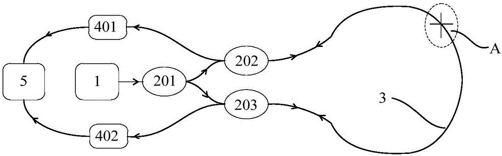
[0033] refer to figure 1, shows a schematic structural diagram of a system for measuring impact locations based on bidirectional detection of optical fiber rings in an embodiment of the present invention. In this embodiment, the impact site measurement system based on optical fiber ring bidirectional detection includes: a light source 1, a first coupler 201, a second coupler 202, a third coupler 203, a sensing fiber 3, a first detection 401, the second detector 402 and the processor 5. Wherein, the output end of the first coupler 201 is connected with the input end of the second coupler 202 and the input end of the third coupler 203 respectively; The output end of the second coupler 202 is connected with one end of the sens...


PUM


Abstract

The invention discloses a bumping position measuring system and method based on bidirectional detection of a fiber ring. The system comprises a light source, first, second and third couplers, a sensing fiber, first and second detectors and a processor; the first coupler couples first optical signals output by the first source to obtain second and third optical signals; the first detector receives the third optical signal which is transmitted to the second coupler via the sensing fiber and output, the second detector receives the second optical signal which is transmitted to the third coupler via the sensing fiber and output, and the two detectors detect returned optical signals, and output first and second voltage signals respectively; and the processor determines a bumped position according to the first and second voltage signals. According to the invention, the bumped position of an object to be measured can be measured more rapidly and accurately, the system structure is simplified, the system cost is reduced, and conditions are provided for batch application of schemes.

Description

technical field [0001] The invention belongs to the technical field of measurement, and in particular relates to a system and method for measuring an impact site based on bidirectional detection of an optical fiber ring. Background technique [0002] Guidance accuracy is the core index of the anti-missile weapon system. Guidance accuracy evaluation needs to obtain the guidance error data of each effective interception test. The key to obtaining the guidance error is to measure the exact part of the aircraft being intercepted and hit, combined with the speed of the interceptor and the aircraft. , Attitude information, the distance from the relative velocity vector passing through the impact point to the centroid of the target warhead can be calculated, that is, the guidance error. Therefore, the high-precision measurement of the impact position has a wide range of application requirements in the high-speed aircraft interception test, which can provide key technical support fo...

Claims


Application Information

Patent Timeline
Patent Type & Authority Applications(China)
IPC IPC(8): G01D5/353
CPCG01D5/35351
Inventor 王学锋杨勇孙巧英胡常青曾笑尘吴垣春
Owner BEIJING INST OF AEROSPACE CONTROL DEVICES
Why Eureka
Try Eureka