Laser radar navigation method and laser radar navigation device

A technology of laser radar and navigation method, applied in the direction of measurement device, electromagnetic wave re-radiation, utilization of re-radiation, etc., can solve the problems of insufficient detection accuracy and detection speed, high installation accuracy requirements, belt wear, etc., to achieve transmission efficiency and transmission. The effect of high precision, improved service life and stable use

Inactive Publication Date: 2017-05-10
湖南晖龙集团股份有限公司
View PDF6 Cites 5 Cited by
  • Summary
  • Abstract
  • Description
  • Claims
  • Application Information

AI Technical Summary

Problems solved by technology

[0003] At present, when the laser radar navigation device is used for detection, the belt is generally used to drive the pulley to rotate, and the pulley then drives the laser to rotate, so as to realize the multi-directional detection of the laser. However, in the process of use, the belt is prone to wear and tear. When it is worn, its transmission efficiency and The transmission stability will be affected, which in turn will affect the performance and service life of the laser radar device. If the belt is replaced regularly, the cost of use will increase. At present, the laser of the laser radar navigation device obtains the detection data and adopts the photoelectric transmission method Data transmission, and photoelectric transmission not only requires high installation accuracy, but also is prone to external interference during the transmission process, and its detection accuracy is difficult to guarantee; in addition, the angle detection module of the current laser radar navigation device usually uses a photoelectric encoder sensor, a photoelectric encoder sensor The requirements for the process are particularly high, and the detection accuracy and detection speed are not enough; in addition, in the current laser radar navigation device, the laser is generally powered by a brushed motor and a feed slip ring. The brushes and feed slip rings of brushed motors are prone to wear and tear, which affects the service life of the lidar device

Method used


Image

  • Laser radar navigation method and laser radar navigation device
  • Laser radar navigation method and laser radar navigation device

Examples


Embodiment 1

[0041] The present invention provides a kind of lidar navigation method, and this method comprises the following steps:

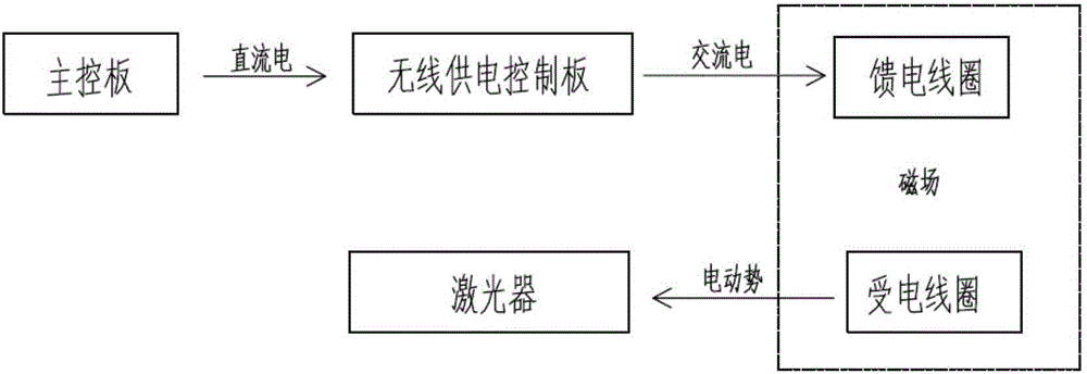
[0042] The main control structure sends a start command to the driving structure and the distance detection device, the driving structure drives the drive plate to rotate, and drives the distance detection device to rotate from the initial orientation and detect the object in front to obtain distance data in different orientations, The angle detection device detects the offset angle between the different orientations of the distance detection device and the initial orientation to obtain angle data, wherein the power supply for the distance detection device adopts a wireless power supply method;

[0043] The main control structure receives distance data and angle data, and fuses the distance data and angle data of each orientation to obtain the fusion data of each orientation;

[0044] PC, which will receive all fusion data and generate point cloud data;

...

Embodiment 2

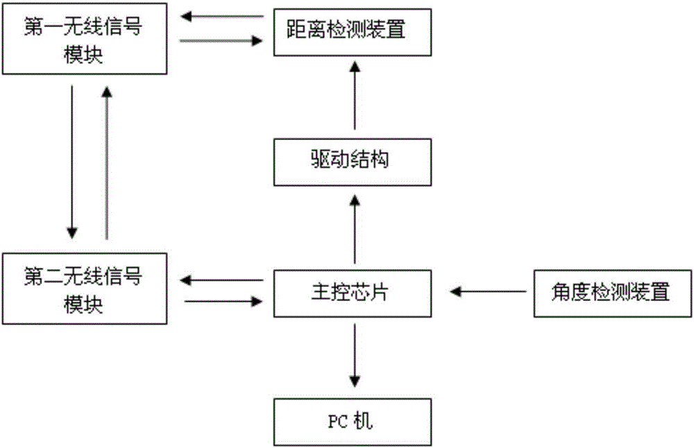
[0061] The present invention provides a laser radar navigation device, comprising:

[0062] A drive structure, the drive structure includes a drive motor, a connection plate and a drive base plate, and the drive base plate is connected to the drive motor through the connection plate;

[0063] a distance detection device, used to detect and transmit distance data, the distance detection device is fixedly installed on the drive base;

[0064] An angle detection device for detecting and transmitting angle data;

[0065] The main control structure includes a motor fixing board, a main control board, and a main control chip installed on the main control board, a motor driver chip, and a MOS tube driver stage, and the main control chip is used to transmit angle data to the motor driver chip , further for receiving and fusing the distance data and the angle data;

[0066] The PC is used to receive all fusion data and generate point cloud data, and is also used to overlap and splice...


PUM


Abstract

The invention discloses a laser radar navigation method and a laser radar navigation device. A main control structure is used to transmit a starting instruction to a driving structure and a distance detection device, and a driving structure is used to drive a driving board to rotate, and is used to drive the distance detection device to rotate from an initial azimuth to detect an object disposed in front of the distance detection device, and the distance data at different azimuths is acquired. An angle detection device is used to detect deviation angles between the different azimuths and the initial azimuth of the distance detection device to acquire angle data. The main control structure is used to receive the distance data and the angle data, and is used to integrate the distance data and the angle data of every azimuth to acquire the integrated data of every azimuth. A PC is used to receive all of the integrated data to generate point cloud data. The PC is used to superpose and splice the point cloud data, and is used to generate a map after removing superposed data, and then a navigation function is realized by combining with a navigation algorithm.

Description

technical field [0001] The invention belongs to the field of laser radar, in particular to a laser radar navigation method and device. Background technique [0002] Lidar technology is an active remote sensing detection technology that integrates laser technology with atmospheric optics, radar technology, optical-mechanical-electrical integration, and computer technology. It has high sensitivity and resolution, rich information, strong anti-interference ability, and concealment. Good features. Lidar technology has been widely used in various civil and military applications such as traffic speed measurement, vehicle collision avoidance, non-destructive testing, and robot vision systems. [0003] At present, when the laser radar navigation device is used for detection, the belt is generally used to drive the pulley to rotate, and the pulley then drives the laser to rotate, so as to realize the multi-directional detection of the laser. However, in the process of use, the belt ...

Claims


Application Information

Patent Timeline
Patent Type & Authority Applications(China)
IPC IPC(8): G01S17/58
CPCG01S17/58
Inventor 李景龙李朝晖
Owner 湖南晖龙集团股份有限公司
Why Eureka
Try Eureka