
Method for predicting milling stability based on Gear formula

A stable and milling technology, applied in the direction of program control, instrumentation, electrical digital data processing, etc.

Inactive Publication Date: 2017-05-10
TAIYUAN UNIVERSITY OF SCIENCE AND TECHNOLOGY
View PDF4 Cites 23 Cited by
  • Summary
  • Abstract
  • Description
  • Claims
  • Application Information

AI Technical Summary

Problems solved by technology

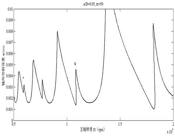
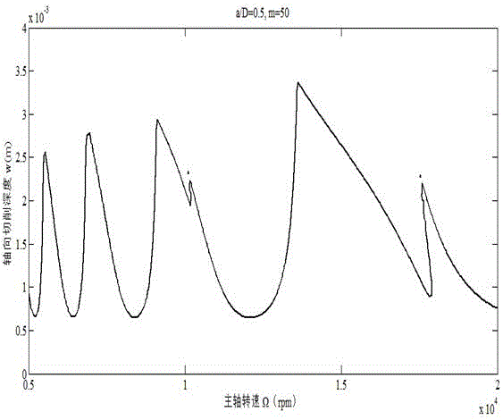
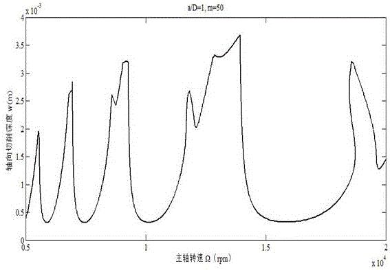
[0003] In order to solve the problems existing in the traditional calculation method for predicting milling stability, the present invention proposes a method based on linear multi-step method using Gear formula to predict milling stability, thereby improving calculation efficiency and calculation accuracy, and realizing high-speed precision cutting

Method used


Image

  • Method for predicting milling stability based on Gear formula
  • Method for predicting milling stability based on Gear formula
  • Method for predicting milling stability based on Gear formula

Examples


Embodiment Construction

[0083] In order to make the present invention clearer, the present invention is further described in detail. It should be understood that the specific embodiments described here are only used to explain the present invention, not to limit the present invention.

[0084] The present invention covers any alternatives, modifications, equivalent methods and schemes made on the spirit and scope of the present invention as defined by the claims. Further, in order to make the public have a better understanding of the present invention, some specific details are described in detail in the detailed description of the present invention below. The present invention can be fully understood by those skilled in the art without the description of these detailed parts.

[0085] The present invention comprises the following steps:

[0086] Step 1): Build a system dynamics model considering regenerative flutter:

[0087]

[0088] In formula (1), M, C and K are the modal mass matrix, modal...


PUM


Abstract

A method for predicting milling stability based on Gear formula is used mainly for selecting reasonable cutting parameters for processing parts and is characterized in that forced periodic vibration is discretized into equally spaced small regions by using Gear formula so as to obtain a transfer matrix of a milling system, a characteristic value of the transfer matrix of the milling system is judged through Fourier theory so as to predict stability of the milling system, computing efficiency and computing precision are improved, and theoretical support is provided for manufacture technicians to select reasonable cutting parameters to improve surface quality of a part. In high-speed numerical control processing, reasonable cutting parameters are selected according to stable lobe graphs, it is ensured that high-speed efficient processing is achieved without fluttering, processing parameters are optimized, high surface quality is obtained, and precision processing is achieved.

Description

technical field [0001] The invention belongs to the field of advanced manufacturing technology, and in particular relates to a method for predicting milling stability based on the Gear formula in a linear multi-step method, which is mainly used for selecting reasonable cutting parameters for processing parts. Background technique [0002] With the rapid development of modern industry, the complexity of parts in aviation, aerospace, shipbuilding and automobiles and other fields is getting higher and higher, the requirements for surface quality are stricter, and the requirements for CNC machining capabilities are also greatly improved. High-speed cutting technology has emerged as the times require. However, the selection of its processing parameters is closely related to the part itself, and is also affected by the cutting process. Sometimes the selection of cutting parameters is too conservative, which makes it difficult for the machine tool to give full play to its performan...

Claims


Application Information

Patent Timeline
Patent Type & Authority Applications(China)
IPC IPC(8): G05B19/406G06F17/50
CPCG05B19/406G05B2219/49074G05B2219/49108G06F30/20
Inventor 曹启超杜娟刘丽琴陈峙孙胜博宁晓琦
Owner TAIYUAN UNIVERSITY OF SCIENCE AND TECHNOLOGY
Learn More