Integratable bus power supply circuit

A technology of power supply circuit and bus, applied in the field of integrated bus power supply circuit, can solve the problems of poor power supply characteristics, difficult to determine and grasp the constant current value, unfavorable integration, etc., achieve high-precision measurement or detection characteristics, and realize measurement or detection properties, good consistency and the effect of temperature properties

Active Publication Date: 2017-05-10
CRM ICBG (WUXI) CO LTD
View PDF5 Cites 9 Cited by
  • Summary
  • Abstract
  • Description
  • Claims
  • Application Information

AI Technical Summary

Problems solved by technology

[0009] Generally speaking, the existing technology mainly has the following three problems: 1. If it is built with a dedicated chip or discrete components, the cost is high, and if it is integrated in a slave chip, the process requirements are relatively harsh, which is not conducive to integration; 2. 1. When the constant current source is used, there is a problem that the constant current value is very difficult to determine and grasp. It is only suitable for some slave circuits whose power consumption has been relatively uniform and stable, and is not suitable for the power consumption of the slave circuit. In some special cases, the power consumption will suddenly increase (such as when the smoke detection circuit is alarming), and the use of a constant current source also has the startup speed of the slave circuit (affecting the factory coding speed during factory production) and energy usage. 3. Usually, the voltage regulator module uses the voltage regulator tube to generate the slave power supply through a first-level LDO (or directly uses the breakdown voltage of the voltage regulator tube as the slave power supply, but the characteristics of the power supply generated in this way will be more poor), which not only has a complex structure, but also will cause the slave power supply to be limited by the characteristics of the Zener tube and the process conditions, and cannot be widely applied to various slave circuits with different power requirements.

Method used


Image

  • Integratable bus power supply circuit
  • Integratable bus power supply circuit
  • Integratable bus power supply circuit

Examples


Embodiment Construction

[0027] In order to describe the technical content of the present invention more clearly, further description will be given below in conjunction with specific embodiments.

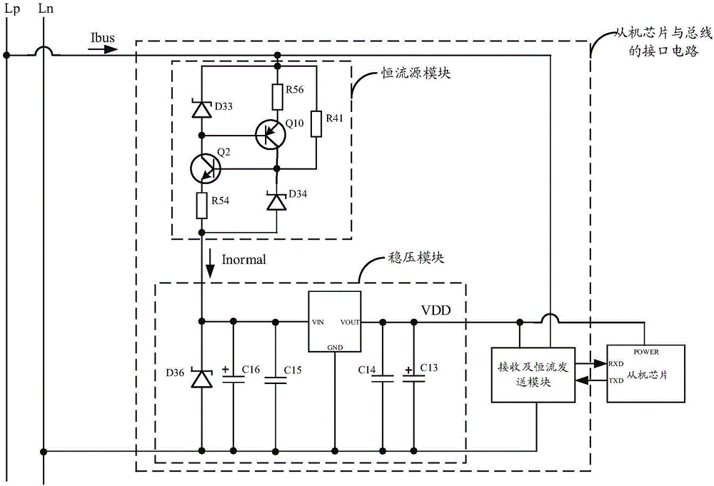
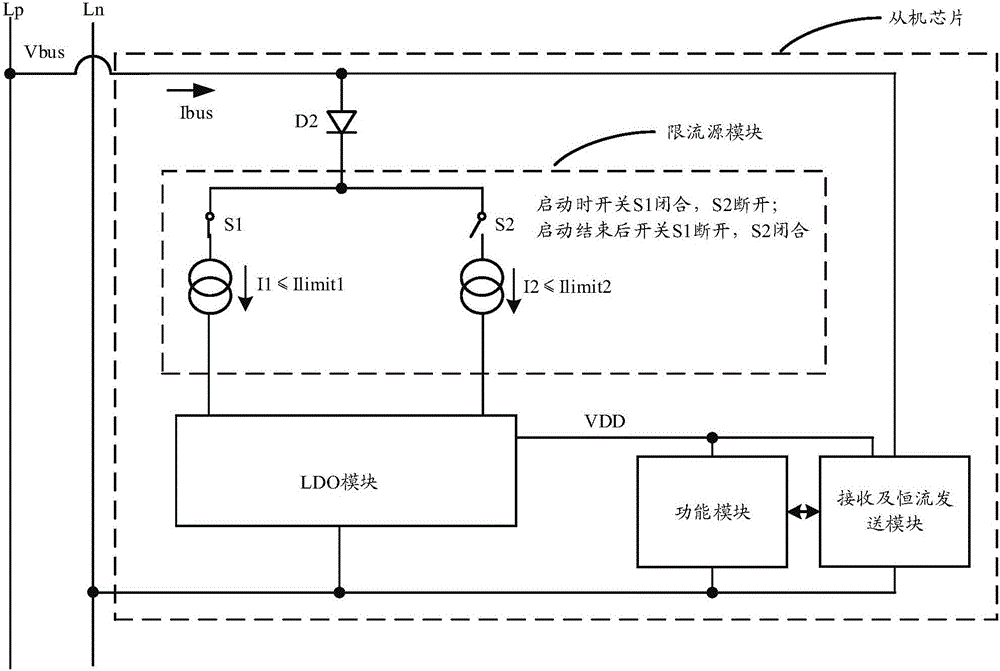
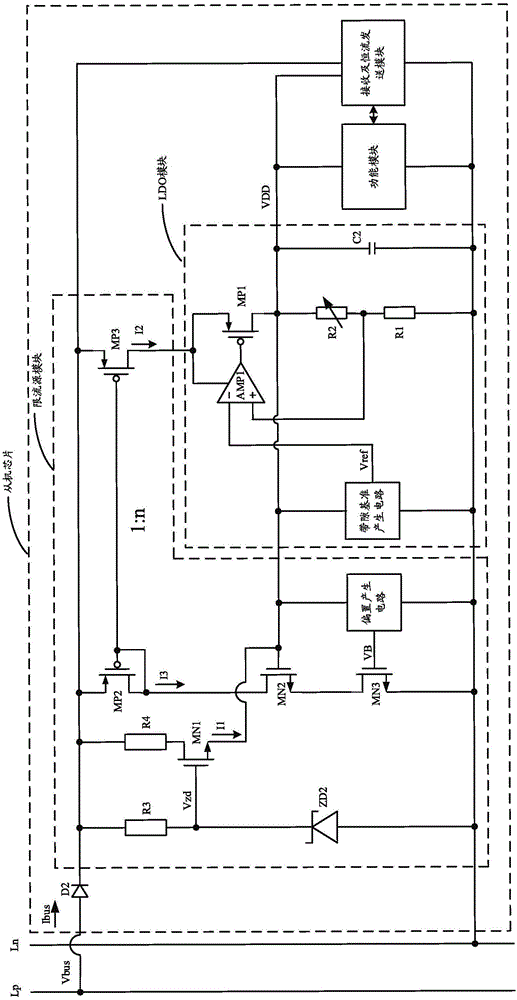
[0028]The bus power supply circuit that can be integrated includes a current limiting source module, an LDO module, a function module, a receiving and constant current sending module and a second diode, and the current limiting source module is connected to the bus negative line Ln, the described The cathode of the second diode, the receiving and constant current sending module are connected to the LDO module, and the LDO module is connected to the functional module and the receiving and constant current sending module respectively , the functional module is connected to the receiving and constant current sending module, and the anode of the second diode is connected to the positive bus line Lp.

[0029] In a preferred embodiment, the current limiting source module includes a second P-type MOS transistor, a...


PUM


Abstract

The invention relates to an integratable bus power supply circuit which comprises a current limiting source module, a LDO (low dropout regulator) module, a function module, a receiving and constant current transmitting module and a second diode. The current limiting source module is respectively connected with a bus cathode line Ln, a cathode of the second diode, the receiving and constant current transmitting module and the LDO module, the LDO module is respectively connected with the function module and the receiving and constant current transmitting module, and the function module is connected with the receiving and constant current transmitting module. The integratable bus power supply circuit is suitable for current CMOS (complementary metal oxide semiconductor) processes, easy to integrate and low in cost; requirements on limiting bus impact current are met; a power source provided to the function module has high uniformity and good temperature characteristics and is unaffected by process factor.

Description

technical field [0001] The present invention relates to the technical field of bus power supply, in particular to the technical field of integrated bus power supply, and specifically refers to an integrable bus power supply circuit. Background technique [0002] In the bus power supply technology, the master and a certain number of slaves (confirmed with different IDs) are connected through two cables, and all the slaves are connected to the bus in parallel and obtain power through the bus. At the same time, the bus is also used as the master and Signal lines for slaves to communicate with each other. When the master sends data to the slave, it adopts the bus voltage modulation method, that is, changes the bus voltage value to transmit data; and when the slave sends data to the master, it uses the bus current modulation method, that is, the slave passes through the slave bus. An additional amount of current is drawn to transfer data. Through the bus power supply and commun...

Claims


Application Information

Patent Timeline
IPC IPC(8): G05F3/26
CPCG05F3/262
Inventor 曾洁琼张天舜罗先才邱旻韡周宇捷奚辛茹
Owner CRM ICBG (WUXI) CO LTD
Why Eureka
Try Eureka