A battery pole piece cutting method and a battery core assembly method comprising the method
An assembly method and battery cell technology, applied in electrode manufacturing, secondary battery, secondary battery manufacturing, etc., can solve the problems of complicated assembly process of laminated battery core, inability to balance speed and performance, poor product consistency, etc. Degeneracy and continuity, reducing equipment automation costs, and the effect of low equipment costs
- Summary
- Abstract
- Description
- Claims
- Application Information
AI Technical Summary
Problems solved by technology
Method used
Image
Examples
Embodiment 1
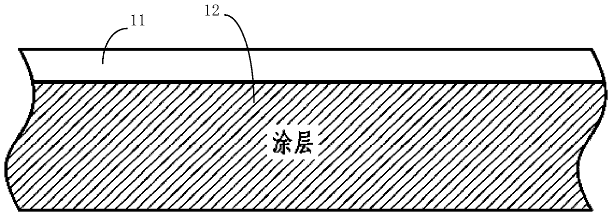
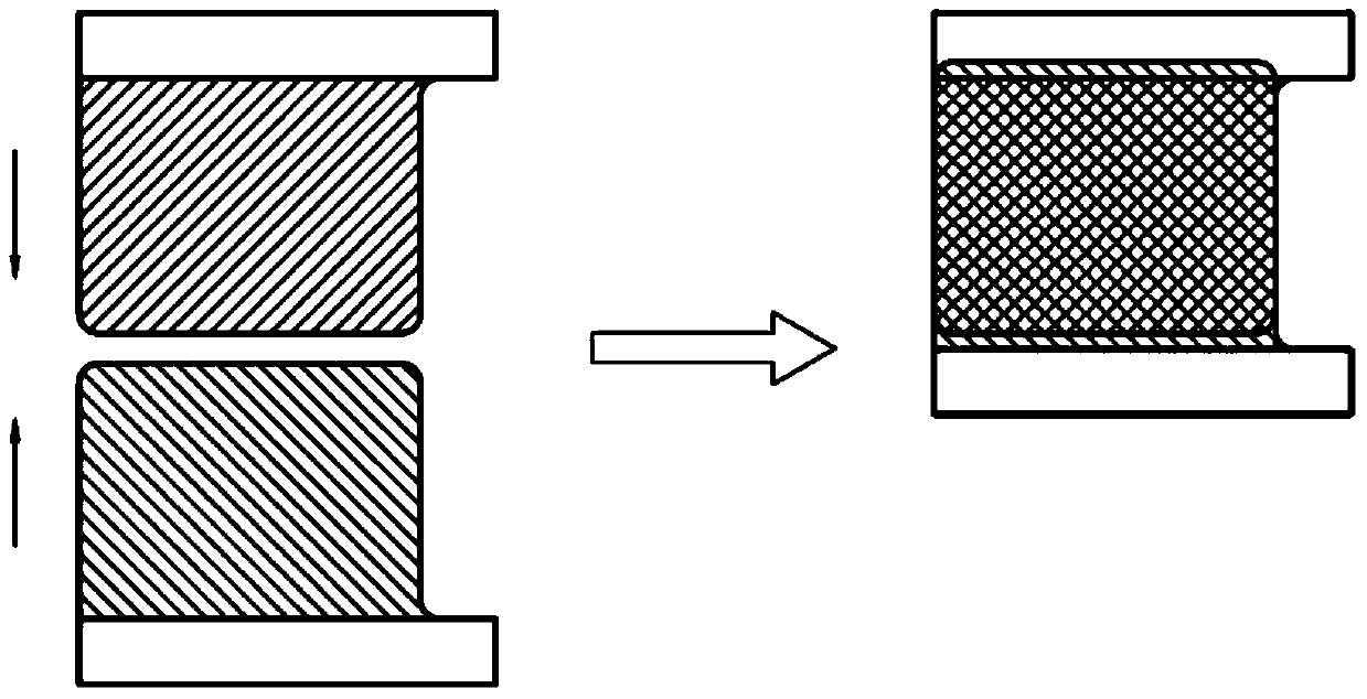
[0074] After coating, the pole piece film roll before slicing (take the positive pole piece film roll as an example, and the negative pole piece film roll is treated similarly) as figure 1 As shown, the schematic diagram of the battery cell assembly to be completed is shown in image 3 shown.
[0075] The specific steps of the battery pole piece cutting method are as follows:
[0076] a) Pole film roll design
[0077] Such as Figure 7 shown, according to image 3 Design the cutting area 72, the reserved area 71 (including the coating area and the upper tab blank area), and the connecting area 73 on the pole piece film roll, wherein the shape of the reserved area is that the pole piece is on the pole piece. The shape that is periodically arranged on the film roll, and the part where the adjacent pole pieces are connected is called the connection area, and the cutting area is the shape of the area to be cut after removing the reserved area on the pole piece film roll;
[0...
Embodiment 2
[0087] After coating, the pole piece film roll before slicing (take the positive pole piece film roll as an example, and the negative pole piece film roll is treated similarly) as figure 1 As shown, the schematic diagram of the battery cell assembly to be completed is shown in image 3 shown.
[0088] The battery cores were assembled in the same manner as in Example 1, except that laser cutting was used instead of die-cutting.
Embodiment 3
[0090] After coating, the pole piece film roll before slicing (take the positive pole piece film roll as an example, and the negative pole piece film roll is treated similarly) as figure 1 As shown, the schematic diagram of the battery cell assembly to be completed is shown in image 3 shown.
[0091] The battery cores were assembled in the same manner as in Example 1, except that a circular knife die-cutting method was used instead of die-cutting to remove waste.
[0092] Wherein, the structure of the die-cutting of the circular knife is as Figure 12 As shown, wherein, the upper roll is a knife roll 1, and the knife roll is provided with a knife mold 2, and the knife mold 2 is arranged at intervals according to the above-mentioned pole piece film roll design, and the shape of the knife mold 2 is the same as that in Example 1. The cutter molds have the same shape, and brushes or rubber felts can be installed at the intervals to clean the fracture and surface. The middle of ...
PUM
 Abstract
Description
Claims
Application Information
 - R&D
- Intellectual Property
- Life Sciences
- Materials
- Tech Scout
- Unparalleled Data Quality
- Higher Quality Content
- 60% Fewer Hallucinations
Browse by: Latest US Patents, China's latest patents, Technical Efficacy Thesaurus, Application Domain, Technology Topic, Popular Technical Reports.
© 2025 PatSnap. All rights reserved.Legal|Privacy policy|Modern Slavery Act Transparency Statement|Sitemap|About US| Contact US: help@patsnap.com


