Mixed type surface texturing tool

A surface texture and hybrid technology, applied in lathe tools, manufacturing tools, tool holder accessories, etc., can solve the problems of severe friction in the cutting zone of the cutting speed of the processed material, increased tool wear, human body and environmental hazards, etc. , to achieve the effect of improving the uneven distribution of the lubricating film, reducing the interface friction, improving the durability of the tool and the processing accuracy

Active Publication Date: 2017-05-17
NANJING UNIV OF AERONAUTICS & ASTRONAUTICS
View PDF8 Cites 18 Cited by
  • Summary
  • Abstract
  • Description
  • Claims
  • Application Information

AI Technical Summary

Problems solved by technology

In order to reduce tool wear and cutting temperature in traditional cutting, a large amount of pouring is generally used to supply cutting fluid. In many cases, the lubrication and cooling effect of cutting fluid cannot meet the processing requirements and increase the manufacturing cost, causing great harm to the human body and the environment. harm
In the current field of cutting processing, the main reason for limiting the cutting speed of difficult-to-machine materials is the severe friction in the cutting area and the increased tool wear caused by high cutting temperature.

Method used


Image

  • Mixed type surface texturing tool
  • Mixed type surface texturing tool
  • Mixed type surface texturing tool

Examples


Embodiment 1

[0021] The following is a PCD material turning tool, laser processing method, and YLP pulsed fiber laser as an example, combined with figure 1 and figure 2 The specific implementation of the present invention will be described.

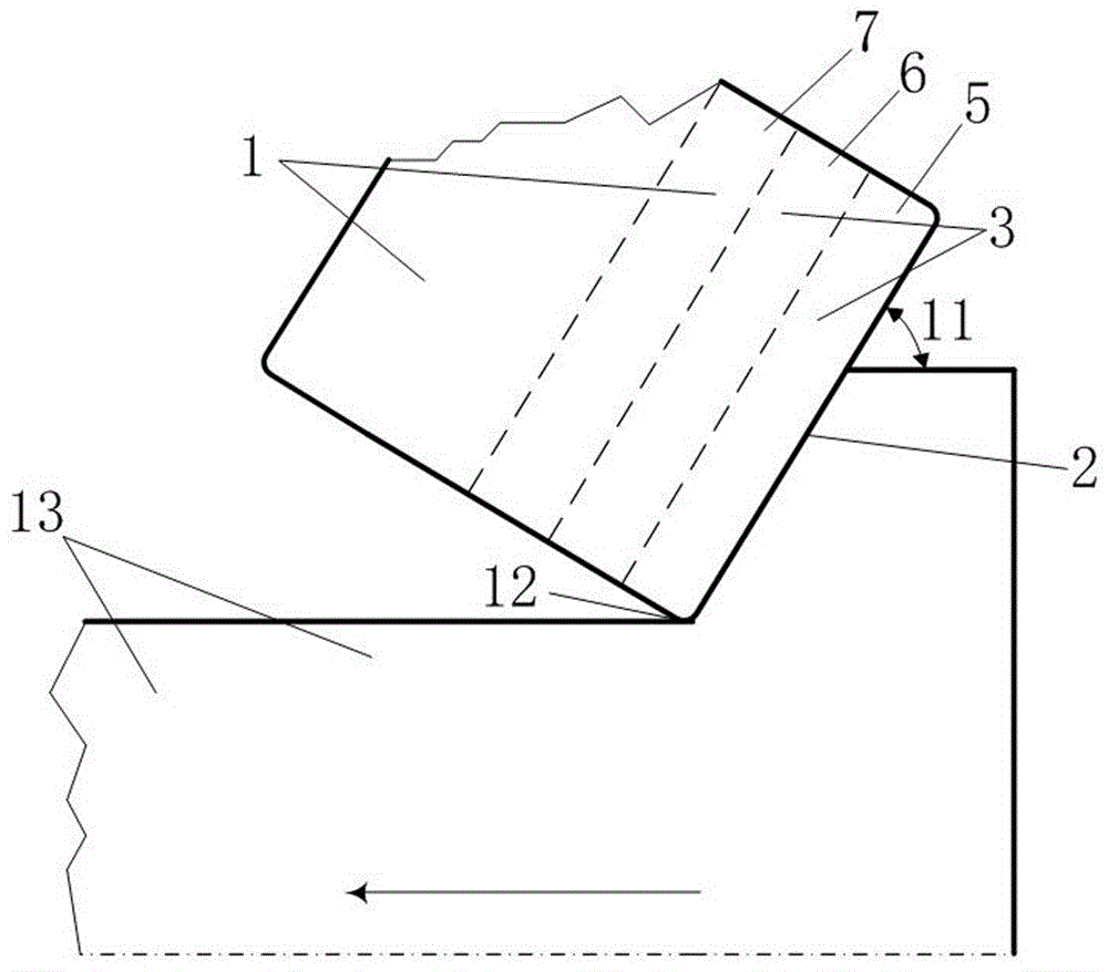
[0022] figure 1 Shown is the relationship diagram of the relative motion between the texture tool and the workpiece 13 to be cut during processing. The main deflection angle 11 is the angle between the cutting edge 2 and the direction of feed movement. During machining, the cutting edge 12 and the cutting edge 2 are in contact with the workpiece 13 to be cut.

[0023] The specific parameters of the PCD turning tool: grain size 10μm, rake angle 0°, relief angle 11°, blade inclination angle 0°, tool tip arc radius 0.5mm, hardness (HV) 800, size 15×15mm.

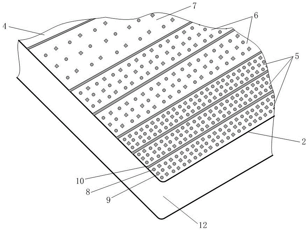
[0024] The embodiment of the present invention provides a PCD turning tool hybrid surface texture design and processing method, including the following steps:

[0025] Step 1. The rake face 1 of ...

Embodiment 2

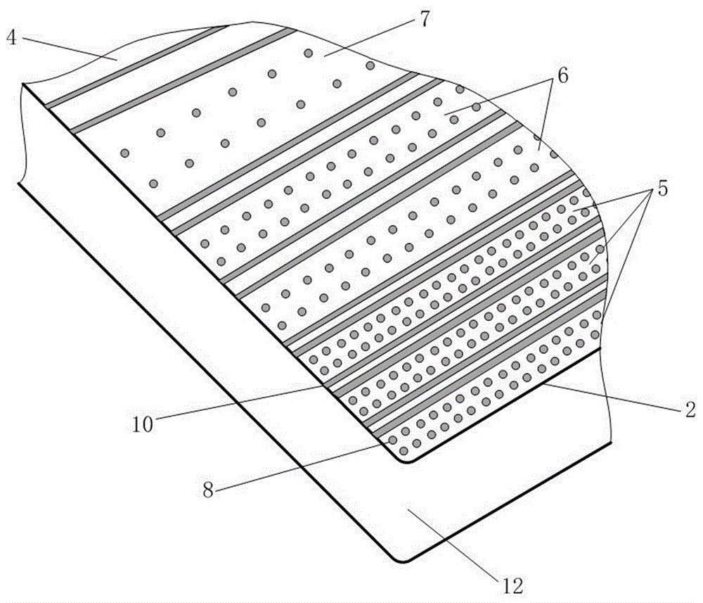
[0030] The following is an example of surface texture processing of YG8 material turning tool using photolithographic electrolytic processing technology, combined with the attached figure 1 and image 3 The specific implementation of the present invention will be described.

[0031] figure 1 Shown is the relationship diagram of the relative motion between the texture tool and the workpiece 13 to be cut during processing. The main deflection angle 11 is the angle between the cutting edge 2 and the direction of feed motion. During machining, the cutting edge 12 and the cutting edge 2 are in contact with the workpiece 13 to be cut.

[0032] The main components and proportions of YG8 turning tools are: cobalt (8%) and tungsten carbide (92%). Specific parameters of YG8 turning tool: rake angle 0°, relief angle 11°, blade inclination angle 0°, tool nose arc radius 0.5mm, surface Rockwell hardness (HRA) 89, size 15×15mm, rake face Ra The value is 0.5 μm.

[0033] The embodiment...


PUM


Abstract

The invention discloses a mixed type surface texturing tool. The mixed type surface texturing tool comprises a rake face and a cutting edge on the rake face. The surface of the rake face is divided into a textured region and an untextured region. The textured region gets close to the cutting edge. The textured region is provided with circular pits, square pits, micro grooves, or a combination of any two forms of circular pits, square pits and micro grooves. Mixed textures of circular pits, square pits and micro grooves are machined in the surface, conducting extrusion and friction with the cutting edge during cutting, of the rake face. The mixed textures can make the speed of a lubricating film perpendicular to the moving direction of the cutting edge be increased and has the improvement on uneven distribution of the lubricating film in the state of boundary lubrication of a traditional tool. The interface friction is reduced. A guarantee is provided for friction reduction of the tool.

Description

technical field [0001] The invention belongs to the technical field of mechanical cutting tools, in particular to a hybrid surface texture tool. Background technique [0002] Friction is the main factor related to the reliability and durability of mechanical equipment. Effectively reducing friction can keep mechanical equipment in a good lubrication state. Therefore, reducing friction has become an urgent requirement to protect the environment and improve efficiency. In order to reduce tool wear and cutting temperature in traditional cutting, a large amount of pouring is generally used to supply cutting fluid. In many cases, the lubrication and cooling effect of cutting fluid cannot meet the processing requirements and increase the manufacturing cost, causing great harm to the human body and the environment. harm. In the current field of cutting processing, the main reason for limiting the cutting speed of difficult-to-machine materials is the severe friction in the cuttin...

Claims


Application Information

Patent Timeline
Patent Type & Authority Applications(China)
IPC IPC(8): B23B27/00
CPCB23B27/00
Inventor 郝秀清李亮陈馨雯崔炜肖思浓何宁
Owner NANJING UNIV OF AERONAUTICS & ASTRONAUTICS
Why Eureka
Try Eureka