Friction stir welding tool and method for repairing keyhole defects using the tool

A technology of friction stir welding and keyhole, which is applied in the direction of manufacturing tools, welding equipment, non-electric welding equipment, etc., can solve the problem of not fundamentally eliminating volume defects, reducing the thickness of the repair area of ​​metal components, and difficult to repair keyhole defects and other problems, to achieve the effect of easy control of material flow at the interface position, lower temperature, and promotion of plastic flow and atomic diffusion

Active Publication Date: 2019-02-19
青岛新动航空科技发展有限公司
View PDF11 Cites 0 Cited by
  • Summary
  • Abstract
  • Description
  • Claims
  • Application Information

AI Technical Summary

Problems solved by technology

[0009] The method of arc preheating friction stir plug repairing welding disclosed in CN101966621B patent document and the method disclosed in CN102500915A patent document adopt T-shaped filler block and needleless stirring head to fill the method of friction stir welding keyhole, both adopt the mode similar to filler block to carry out keyhole welding. The hole defect repair is limited by the thickness of the plate. It is difficult to repair the keyhole defect of the thick plate with large depth by these two methods; in addition, the repair interface is prone to metallurgical bonding, which will reduce the performance of the welded joint
The disadvantage of these two methods is that new keyhole defects will appear after friction stir welding, and the volume defects are not fundamentally eliminated
[0011] The CN103212778A patent document discloses a crack repair method based on friction stir, which only uses a needleless stirring head to repair the defects near the surface of the metal material, but fails to realize the repair along the depth direction of the plate, and the thickness of the repair area of ​​the metal component will be thinned, resulting in Stress concentration, reduced fatigue life of joints

Method used


Image

  • Friction stir welding tool and method for repairing keyhole defects using the tool
  • Friction stir welding tool and method for repairing keyhole defects using the tool
  • Friction stir welding tool and method for repairing keyhole defects using the tool

Examples


Embodiment Construction

[0041] The present invention will be further described below in conjunction with drawings and embodiments.

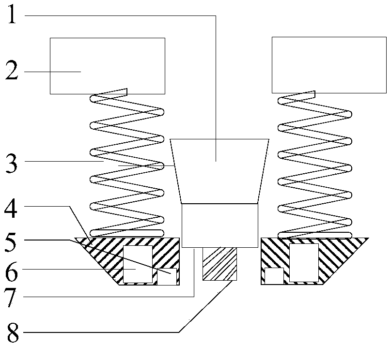
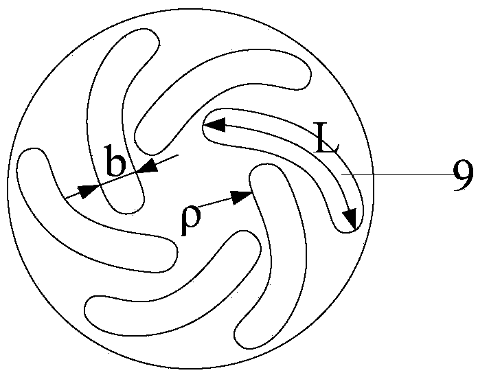
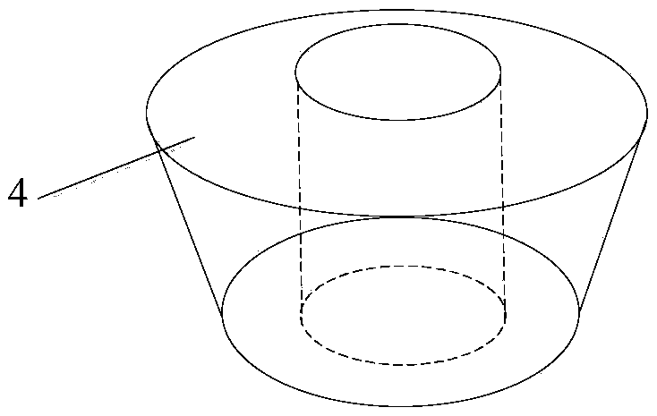
[0042] combine Figure 1 to Figure 4 , The friction stir tool of the present invention includes a stirring head 1 and a stationary shoulder 4 matched with the stirring head. The bottom surface of the stirring needle 8 of the stirring head has six helical grooves 9, and the maximum curvature radius ρ, arc length L and width b of the six helical grooves are respectively 0.7 times, 0.5 times and 0.1 times the diameter of the stirring needle. The static shoulder is in the shape of a truncated cone with a large top and a small bottom. Its inner diameter is 0.1-0.3mm larger than the diameter of the stirring head shoulder 7 of the stirring head, the outer diameter of the lower end is 5-10mm larger than the inner diameter, and the outer diameter of the upper end is 20-50mm larger than the inner diameter. Height and mixing head details ( figure 1 The middle stirring head is loca...


PUM

PropertyMeasurementUnit
thicknessaaaaaaaaaa
diameteraaaaaaaaaa
thicknessaaaaaaaaaa

Abstract

The invention discloses a friction-stir welding tool which is characterized in that a six-helix groove is formed in the bottom surface of a stirring needle of a stirring head; a stationary shaft shoulder is connected with shaft shoulder fixing blocks through springs; the shaft shoulder fixing blocks are fixedly arranged on a welding machine; an electric heating device and a cooling medium passage are arranged and formed in the stationary shaft shoulder; and the electric heating device is arranged inside, close to the stirring head and the cooling medium passage is outside the electric heating device. When the friction-stir welding tool is used to repair a key hole defect, a key hole of a to-be-repaired workpiece is processed to be cylindrical, then continuous filling repair is carried out on the cylindrical key hole by using the stirring heads, the stationary shaft shoulders and filling pieces in different sizes. Compared with the prior art, the friction-stir welding tool has the beneficial effects that the grain size of a repair area is fined, the metallurgical bonding property and the mechanical property are good, the strength is high, the thickness of the repair area is not reduced, no material is spilled, the stress concentration phenomenon is few, and the friction-stir welding tool is free from defect depth limitation and is wide in application scope.

Description

technical field [0001] The invention relates to metal welding, in particular to a friction stir welding tool and a method for repairing keyhole defects with the tool. Background technique [0002] As a new solid-phase welding method, friction stir welding has the advantages of low welding temperature, small deformation and residual stress, and high-quality welded joints. It has been widely used in aerospace, high-speed rail, and ships. During the welding process, a friction stir welding tool consisting of a specially designed shoulder and a stirring head penetrates into the metal component, and friction with the metal component generates frictional heat, which makes the material flow and realizes the connection of the metal component to be welded. [0003] During the friction stir welding process, due to the existence of the stirring pin, a keyhole defect will appear at the end of the welded joint, which will cause weak connection and stress concentration effect, greatly red...

Claims


Application Information

Patent Timeline
Patent Type & Authority Patents(China)
IPC IPC(8): B23K20/12B23K20/24
CPCB23K20/1215B23K20/122B23K20/1255B23K20/24
Inventor 姬书得孟祥晨熊需海龚鹏宋崎胡为张利国刘震磊黄若飞吕赞
Owner 青岛新动航空科技发展有限公司
Why Eureka
Try Eureka