Cooling air path system of unmanned aerial vehicle

A drone and air duct technology, applied in the field of drones, can solve the problems of loud fan noise, large fuselage, limited cavity space, etc., and achieve the effect of efficient physical cooling and large heat dissipation area.

Inactive Publication Date: 2017-05-17
YUNEEC INT (CHINA) CO LTD
View PDF11 Cites 9 Cited by
  • Summary
  • Abstract
  • Description
  • Claims
  • Application Information

AI Technical Summary

Problems solved by technology

[0003] Some heat dissipation components are installed in the existing drones to achieve heat dissipation, but only for some parts to play a partial heat dissipation function, for example, the airflow is introduced into the battery compartment and then exported, only for the battery compartment to dissipate heat. However, there are other components in the drone that also generate a lot of heat, such as motors, chips, etc. The airflow is bound in the battery compartment and cannot dissipate heat from the fuselage as a whole. Therefore, the current cooling compo

Method used


Image

  • Cooling air path system of unmanned aerial vehicle
  • Cooling air path system of unmanned aerial vehicle
  • Cooling air path system of unmanned aerial vehicle

Examples


Embodiment Construction

[0031] In order to make the above objects, features and advantages of the present invention more comprehensible, specific implementations of the present invention will be described in detail below in conjunction with the accompanying drawings.

[0032] In the following description, numerous specific details are set forth in order to provide a thorough understanding of the present invention. However, the present invention can be implemented in many other ways different from those described here, and those skilled in the art can make similar extensions without violating the connotation of the present invention, so the present invention is not limited by the specific implementations disclosed below.

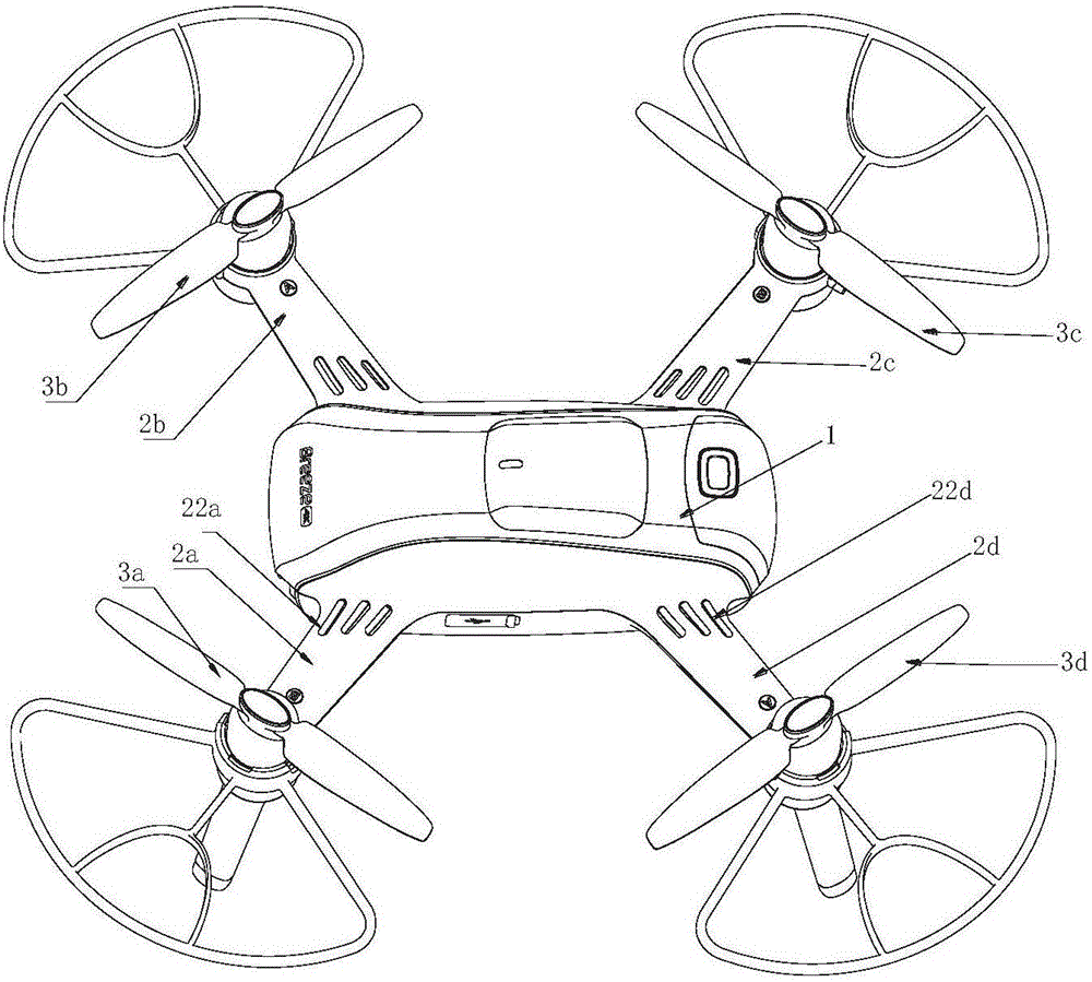
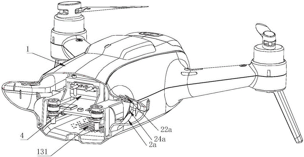
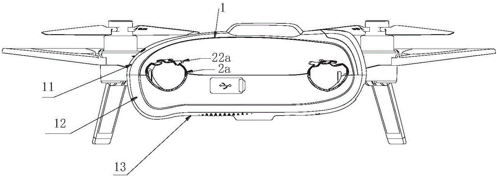
[0033] see Figure 1-5 , in one embodiment, the UAV heat dissipation air duct system includes: an airflow source, an air guide hole, an air duct and an air outlet 131 .

[0034] Wherein, the airflow source is generated by the rotation of blades arranged on each machine arm. The bl...


PUM


Abstract

The invention provides a cooling air path system of an unmanned aerial vehicle. The cooling air path system comprises an airflow source, air guiding holes, an air path and air outlets, wherein the airflow source is generated by rotation of paddles on all vehicle arms, the air guiding holes are formed in the portions, corresponding to paddle tail rotating areas, of the top faces of all the vehicle arms, the air path is a gap channel between the inner wall of a vehicle body and internal modules of the vehicle body, and the air outlets are formed in the position, corresponding to a heating source area, of the bottom of the vehicle body. The airflow source guides airflow into the inner sides of the vehicle arms through the air guiding holes, and the airflow enters the air path, flows through the heating source area and then is exhausted from the air outlets. The cooling air path system of the unmanned aerial vehicle is good in whole vehicle cooling performance and low in noise.

Description

technical field [0001] The invention relates to unmanned aerial vehicle technology, in particular to an unmanned aerial vehicle heat dissipation air duct system. Background technique [0002] Unmanned aircraft, referred to as "UAV", is an unmanned aircraft controlled by radio remote control equipment and its own program control device. When the drone is working, it will generate a lot of heat. If the heat is not dissipated in time, the heat accumulation will affect the normal operation of the drone when it is overheated. Long-term overheating will cause damage to the drone or attenuation of its service life. Therefore, a part for heat dissipation is usually provided on the drone. [0003] Some heat dissipation components are installed in the existing drones to achieve heat dissipation, but only for some parts to play a partial heat dissipation function, for example, the airflow is introduced into the battery compartment and then exported, only for the battery compartment to...

Claims


Application Information

Patent Timeline
IPC IPC(8): B64C27/08B64D13/00
CPCB64C27/08B64D13/006B64D2013/0614B64U10/10
Inventor 田瑜江文彦
Owner YUNEEC INT (CHINA) CO LTD
Why Eureka
Try Eureka